C-2.2 Plumbing Appliance Installation
Procedures to install plumbing appliances are not complex but require a great deal of care to ensure that the appliances operate reliably and that each installation has an attractive look. The professional appearance of plumbing appliance installations reflects the skill and knowledge of each plumber.
Code Regulations
Plumbing appliances use electricity or some other form of external power supply. Electrical permits may be required in some areas, and if branch circuits must be installed for the appliances, the work must be done by a registered electrical contractor. Refer to your local jurisdiction for specific regulations that apply to appliance installation.
Installing Garbage Disposal Units
Garburators are requested by some homeowners. Check all local requirements and specific manufacturers’ directions regarding garbage disposal installation.
If a dishwasher is also to be installed, the dishwasher drain hose will be attached to the drain fitting located on the garbage disposer. This helps to flush out the disposal unit during each discharge cycle of the dishwasher.
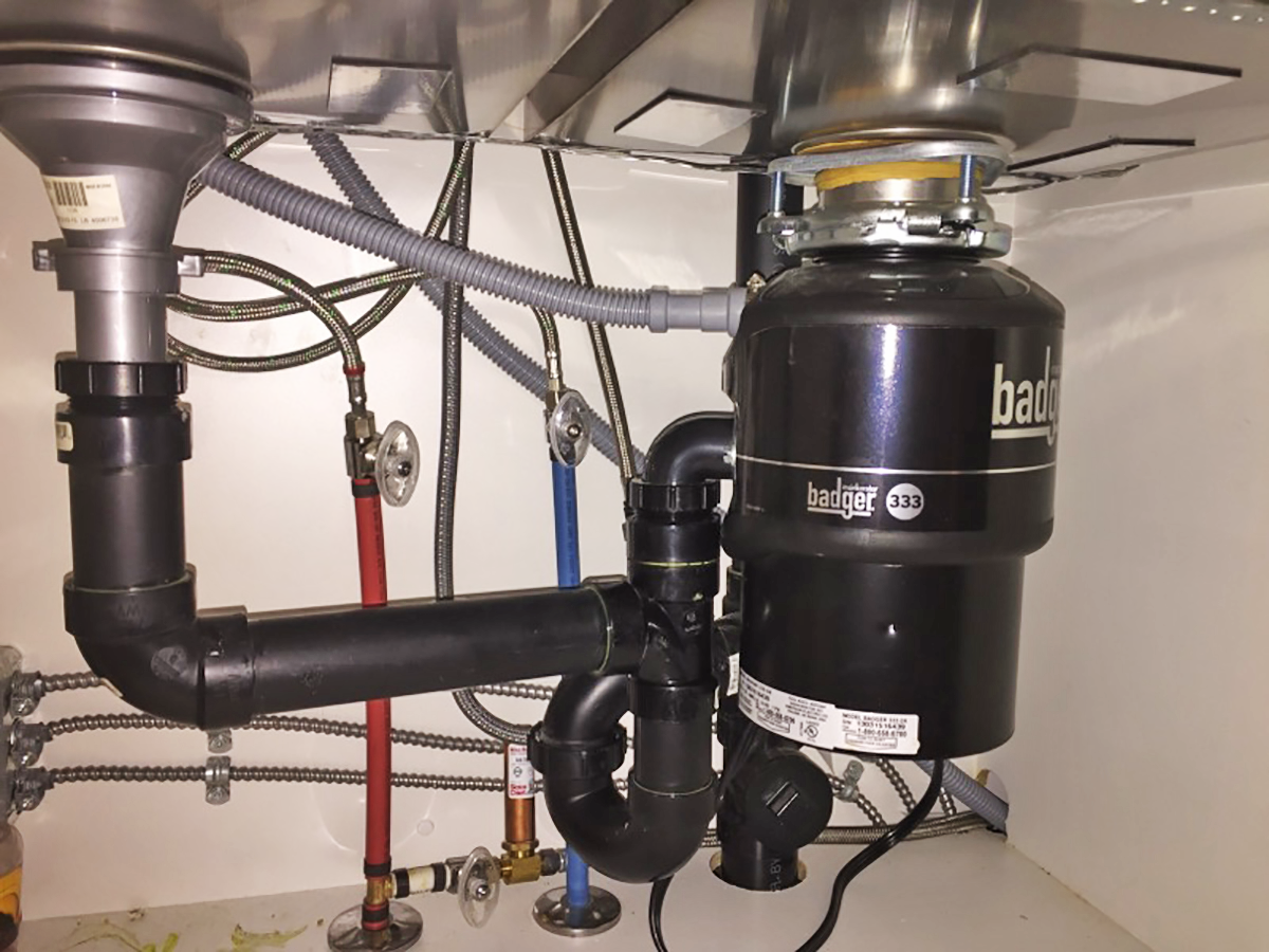
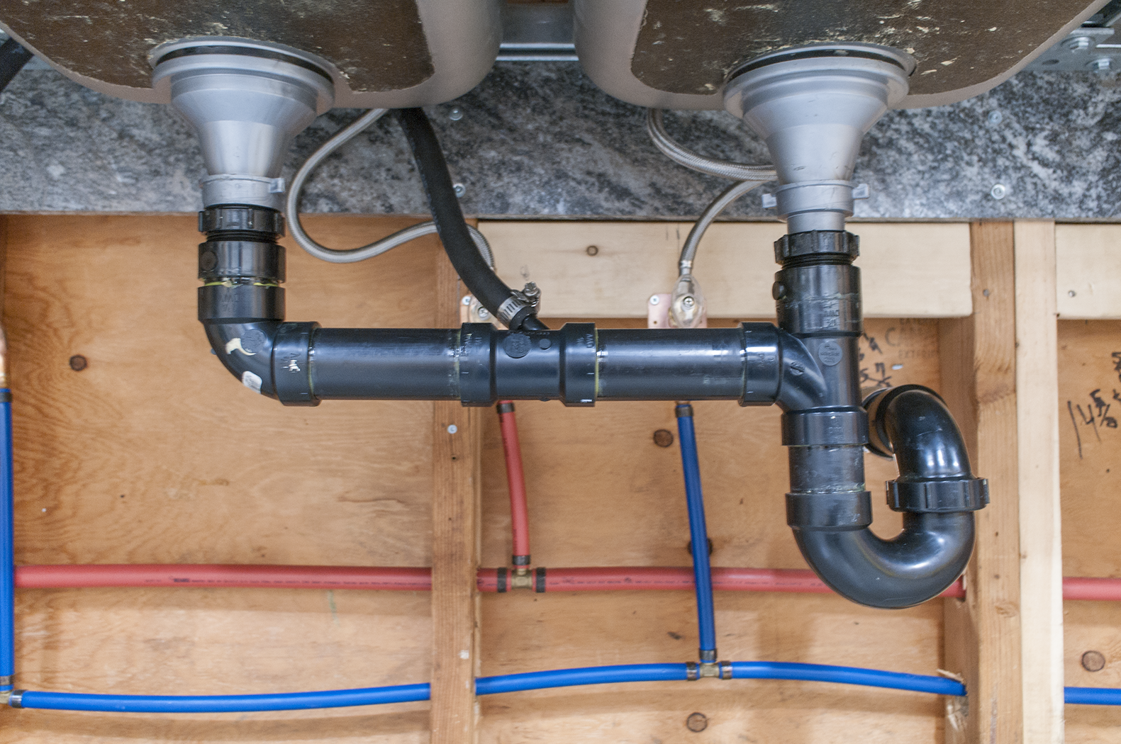
A garbage disposal installed under a single-compartment sink is connected directly to the sink drain outlet. Under a double-compartment sink, the garbage disposal is attached directly under one of the compartments, with an outlet pipe connecting it to the drain of the second compartment (Figure 1).
Some newer sink designs have a third compartment that is intended to be connected to the garbage disposer, and the two sink compartments can be drained either to the disposer or directly to the main drainage piping.
The disposer must be wired to the main junction box or plugged into an electrical outlet below the sink. A control switch should be installed in a more convenient location, usually on the wall above and behind the sink deck. Electrical circuit wiring should be done by an electrician.
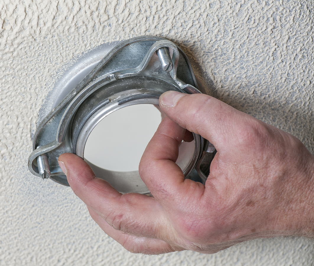
The most common garburator drain outlet is a standard flanged drain without threads. Sealant or a gasket is applied to the underside of the flange, and the drain is dropped into the sink outlet. A collar is slipped onto the extension underneath the sink and three travelling bolts are threaded through the collar (Figure 2). As these bolts are tightened, they force the collar up to the underside of the sink.
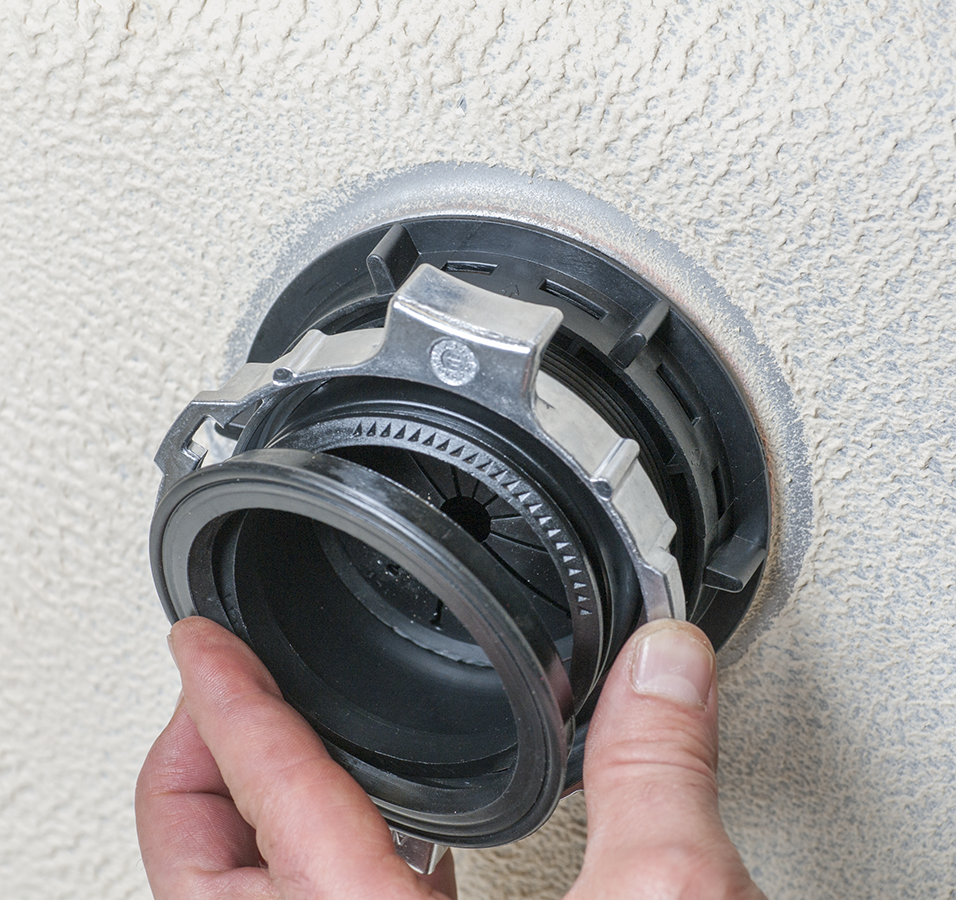
Another style of garburator outlet has a [pb_glossary id=”817″]threaded flange[/pb_glossary] similar to common sink drains (Figure 3).
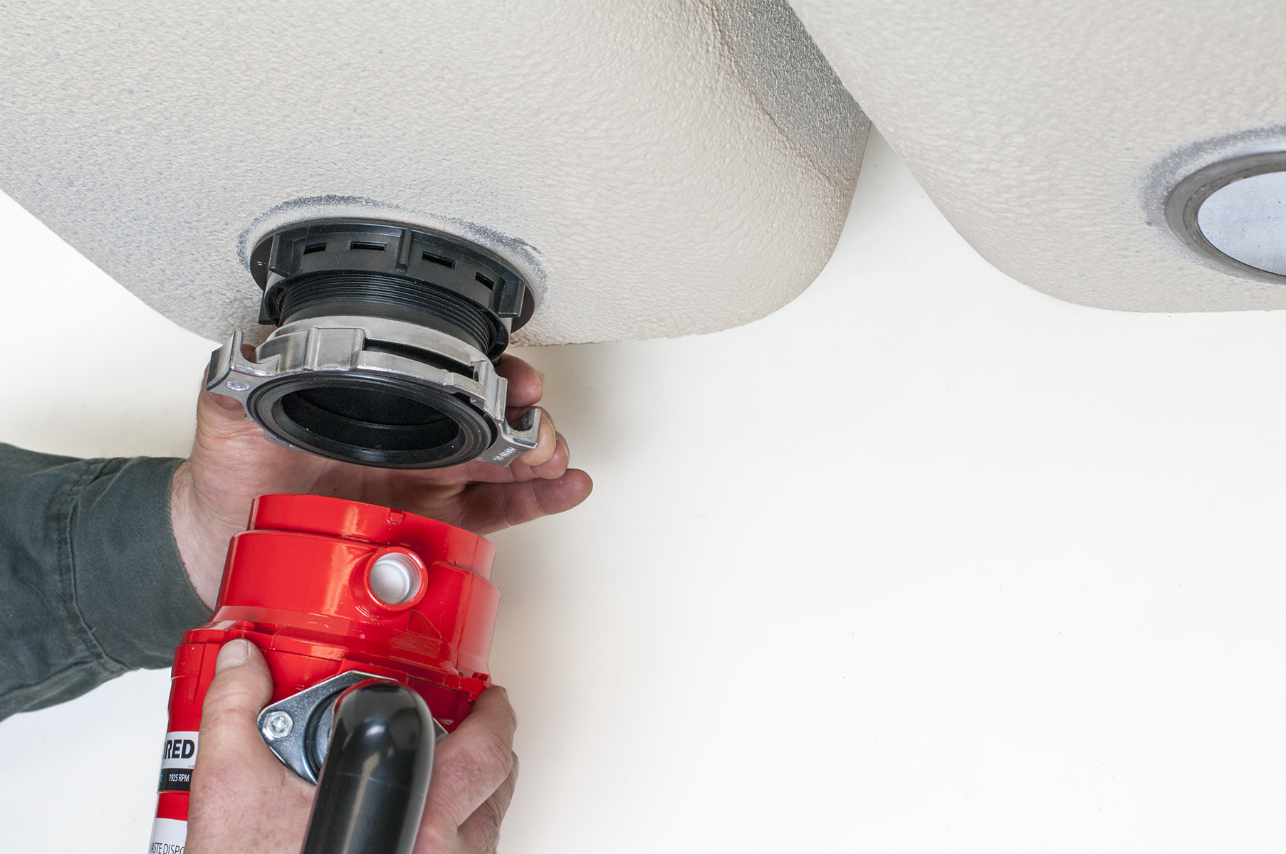
The disposer is mounted onto the collar (Figure 4) and locked in place using the tightening tool provided with the unit.
Installing Dishwashers
When installing a standard built-in dishwasher, the hot water piping should be roughed in so it will meet the dishwasher elbow (or adapter fitting) when the dishwasher is in place. Hot water inlet piping is typically either a flexible braided supply connector or PEX, polyethylene, or copper tubing.
Install a separate stop valve for the dishwasher supply line. The stop should be easily accessible.
The drain hose of the dishwasher is connected to a dishwasher tee or a wye-branch adapter fitting on the outlet pipe of the existing sink drain (Figure 5). If a garbage disposer is connected, the drain hose is connected to the garbage grinder, as described earlier in this learning task.
The dishwasher drain line must rise as high as possible and be securely fastened under the countertop before connecting to the sink’s outlet pipe. This is intended to prevent possible backup of the sink drain (backflow) from flowing into the dishwasher.
Dishwashers may be wired from a junction box or plugged into a conveniently located ground-fault–protected electrical outlet. Electrical circuit wiring should be done by an electrician.
First, cut a hole in the side of the cabinet between the sink piping and the installation location. Thread the flexible drain hose through the hole and fasten it as high as possible under the cabinet. Attach it to the sink drain fitting with the supplied gear clamp or spring clamp.
Connect a dishwasher elbow or adapter fitting (Figure 6) to the hot water supply inlet on the dishwasher. Slide the dishwasher into place and attach the hot water supply connector to the stop valve.
Level the dishwasher with levelling screws or legs. When it is aligned correctly, fasten the hold-down brackets to the underside of the countertop with [latex]\tfrac{1}{2}[/latex] in. (13 mm) wood screws. (Note: Before installing, ensure that the screws will not penetrate the countertop.)
Cycle the dishwasher through the washing sequence, and check that all drain and supply connections are watertight.

Installing Clothes Washers
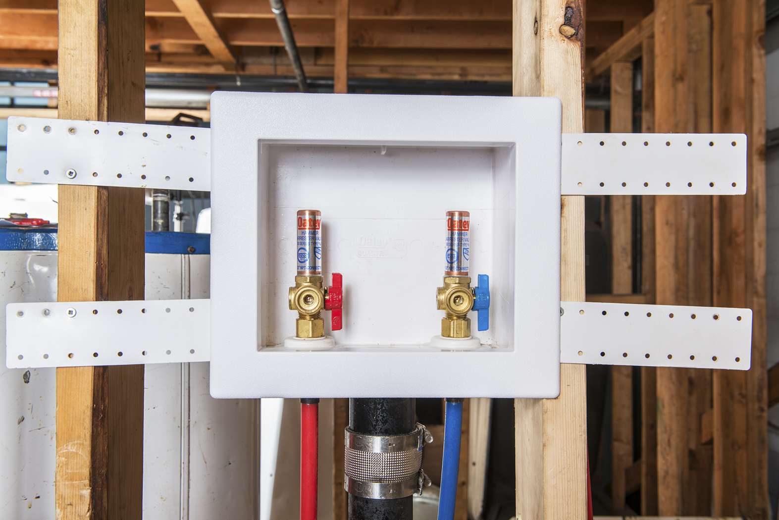
Before installing a clothes washer, rough-in piping should be in place. Standard rough-in drainage piping consists of a minimum 600 mm (24 in.) tall trapped standpipe. Standpipes are required to be a minimum 2 in. (51 mm) diameter, and their inlet must extend above the flood level rim of the washer. Hot- and cold-water supply lines should have risers that extend to a height of approximately 1,100–1,200 mm (42–48 in.). Standard hose bibbs are placed on hot- and cold-water supply lines, or a laundry box (Figure 7) is used to provide a clean and tidy installation.
Slide the washer unit into position and level it. Attach the rubber or braided supply hoses from the inlets on the washer to the hot and cold hose bibbs. Insert the washer’s discharge hose into the top of the standpipe or drain opening in the laundry box. Cut the drain hose to the desired length, if required. Clothes washers may also drain to a laundry tray if no drain standpipe is available. Water-hammer arrestors are installed on both hot- and cold-water supply lines and act to prevent shock caused by the rapid closing of valves inside the clothes washer.
Clothes washers can be wired into the main junction box or plugged into a conveniently located electrical outlet. Electrical circuit wiring should be done by an electrician.
Cycle the clothes washer through the full sequence and check that all drain and supply connections are watertight.
Installing Electric Water Heaters
Unlike gas water heaters, electric heaters can be installed inside an unventilated space (e.g., a closet with a closed door) since they do not burn fossil fuel directly and require no combustion air supply or flue vent.

Do not expose a water heater’s exterior to rain or water. Do not touch a water heater that is leaking, wet, or flooded without turning the power supply OFF.
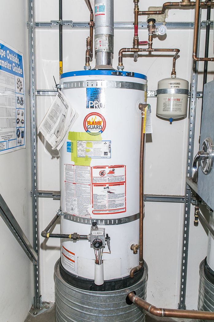
Installing Storage Tank Water Heaters
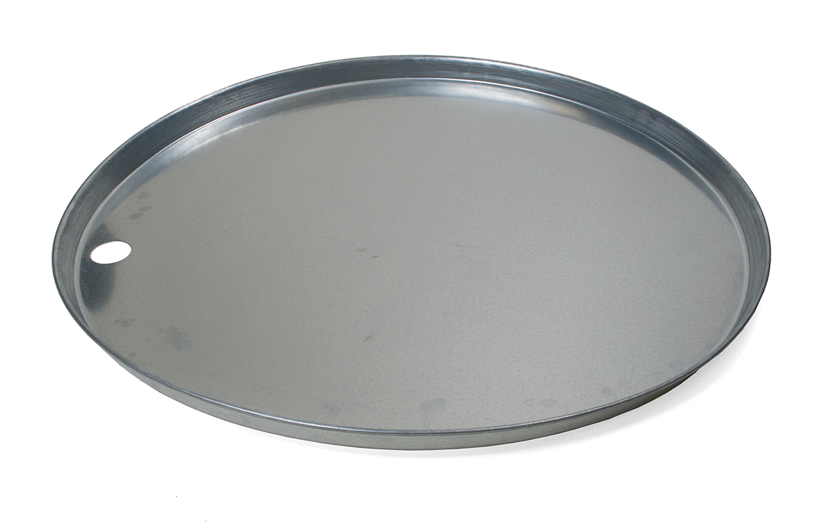
The base for the tank placement must be firm and level. Ensure that the tank is placed on a drain pan (Figure 8) if the floor is constructed of wood.
Place the tank in the proposed location and ensure that access panels, drain fitting, and rating plate information will be accessible and visible after installation.
Next, prepare all threaded adapters required for the tank connections. Most tanks are provided with [latex]\tfrac{3}{4}[/latex] in. (19 mm) NPS galvanized, plastic-lined, tank nipples. A minimum of 450 mm (18 in.) of copper tubing should be attached to the top of the tank to protect plastic water distribution lines from unnecessary exposure to high temperatures. After that, any variety of approved materials may be used.
Attach [latex]\tfrac{3}{4}[/latex] in. (19 mm) dielectric unions or FIP adapters with 450 mm (18 in.) of copper, as mentioned.
Shutoff valves are required for the supply to every tank, and vacuum relief valves are needed when the tank may be subject to backsiphonage (best practices dictate that all tanks have these). The vacuum-relief valve does not act as a backflow preventer to protect the drinking water; instead, it protects the tank from imploding due to the negative pressure that may be created by backsiphonage.
Finish connecting the cold inlet and hot outlet copper piping to the remainder of the water distribution system, then turn on the cold water to the tank. Ensuring that the drain valve is closed, relieve air from the tank by opening a hot faucet at a nearby fixture. Next, complete the piping for the relief valve discharge port and ensure that it terminates near the pan, floor drain, or other safe location, with a maximum air break of 300 mm (12 in.) (minimum of 38 mm/[latex]1\tfrac{1}{2}[/latex] in.). The drain pan and relief valve piping should drain to a trapped connection to the sanitary drainage system (or storm drainage system, where approved).
Once you are satisfied that all the air is purged from the tank, have an electrician complete the connection to the branch circuit wiring. Ensure that the bonding conductor has been securely fastened to the ground screw in the appliance. Once this is complete, you can turn on the circuit breaker. Tank thermostats usually come preset to 60°C (140°F) and should remain at that maximum temperature for suitable disinfection of bacteria. If scalding is a concern at a fixture, the distribution system should include a tempering device.
If provision for thermal expansion is not already provided, install an adequately sized expansion tank (rated for use with potable water) or thermal expansion relief device (as per manufacturers’ instructions) to comply with code.
In seismic velocity regions (e.g., BC coastal areas), storage tanks must be restrained to prevent them from overturning in the event of an earthquake. Seismic Restraint Kits are available that provide an attractive, secure installation (Figure 9). Typically, restrained tanks are secured on the top [latex]\tfrac{1}{3}[/latex] and the bottom [latex]\tfrac{1}{3}[/latex] of the tank and must be fastened to structural components to ensure their integrity.

Securing perforated steel strapping to drywall is NOT acceptable.
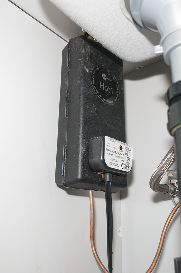
Installing Tankless Water Heaters
Installing piping for tankless heaters is similar to that for electric tank water heaters. Tankless heaters differ in that they are typically wall-mounted (Figure 10) and should be secured according to the manufacturer’s instructions. Tankless heaters also have significant wiring considerations because they draw lots of power to heat the water quickly on demand.
Operating Electric Storage Tank Water Heaters
Once the tank has been filled with water, it will contain no air. When a hot water faucet is turned on, hot water immediately leaves the top of the tank and travels through the piping system until it reaches the faucet. At the same time, new cold water enters the bottom of the tank through the dip tube or bottom fill port.
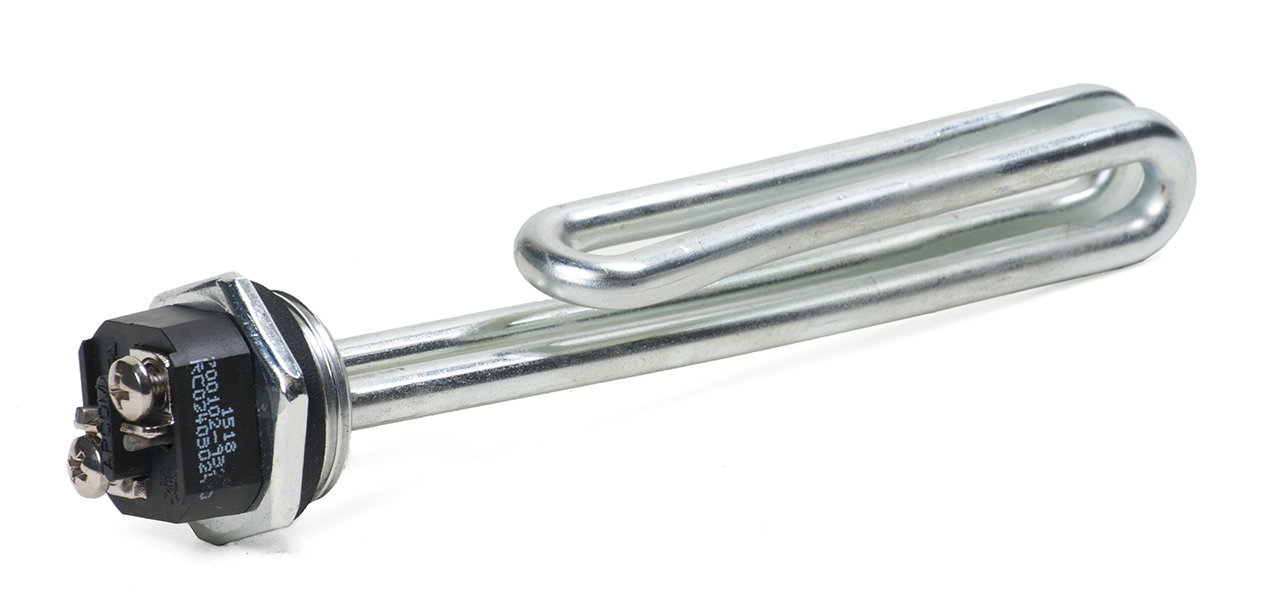
The drawing off of hot water and entry of cold water causes the temperature in the tank to drop; this is sensed by the thermostats, which then activate the elements. The heating of the water is performed by electric elements. Tanks have one or two elements, depending on their design. Electric immersion elements are similar to electric stove burners except they have elongated shapes and are designed to be immersed in water (Figure 11).
Elements are controlled by upper and lower thermostats. The thermostats read the water temperature through contact with the side of the tank and turn the elements on or off.
Elements instantly burn out if there is no water inside the tank. Elements can also fail for other reasons and can often be replaced. In two-element tanks, if the lower element burns out, the amount of hot water is greatly reduced. If the upper element burns out, the lower element stops receiving electric signals, so neither element works, and no hot water is available.
Both elements are never on at the same time unless specific wiring is changed. The upper thermostat is the main controller; it turns on the upper element until the top two-thirds of the tank reaches the temperature setting. After that, the upper thermostat turns off the upper element and sends power to the lower thermostat, which turns on the lower element. The lower element is energized until the entire tank reaches the preset temperature setting.
Residential water heater thermostats can be manually set to temperatures between 32 and 65°C (90–150°F) but should always be kept at a minimum of 60°C (140°F) to kill bacteria.
Tempered water (usually max. 49°C/120°F) can then be delivered to fixtures through a master mixing valve or point-of-use tempering devices.
 Self-Test C-2.2 Plumbing Appliance Installation
Complete Self-Test C-2.2 and check your answers.
If you are using a printed copy, please find Self-Test C-2.2 and Answer Key at the end of this section. If you prefer, you can scan the QR code with your digital device to go directly to the interactive Self-Test.

References
Skilled Trades BC. (2021). Book 2: Install fixtures and appliances, install sanitary and storm drainage systems. Plumber apprenticeship program level 2 book 2 (Harmonized). Crown Publications: King’s Printer for British Columbia.
Trades Training BC. (2021). C-2: Install appliances. In: Plumber Apprenticeship Program: Level 2. Industry Training Authority, BC.
Media Attributions
All figures are used with permission from Skilled Trades BC (2021) unless otherwise noted.
A flexible tube that connects a dishwasher to a drainage system to remove wastewater. (Section C-2.2)
A type of sink drain connection where a flat, circular rim (flange) helps secure the drain to the sink. (Section C-2.2)
A shutoff valve used to control the flow of water to an appliance, such as a dishwasher or clothes washer. (Section C-2.2)
A device installed on water supply lines to absorb shock and prevent noise caused by the sudden closing of valves. (Section C-2.2)
A shallow tray placed beneath a water heater to collect and direct water from leaks or pressure relief discharge. (Section C-2.2)
A specialized plumbing fitting that prevents galvanic corrosion between different metal pipes. (Section C-2.2)
A valve that prevents a water heater tank from collapsing due to negative pressure caused by backsiphonage. (Section C-2.2)
When dirty water flows backward into clean water pipes by accident. This can happen if water pressure drops, like when a water main breaks or a lot of water is used at once. It can let harmful stuff, like bacteria or chemicals, get into the drinking water supply. (Section C-2.2)
A device that controls the temperature of a water heater by regulating the activation of heating elements. (Section C-2.2)
A small tank installed in a water heating system to absorb excess pressure caused by thermal expansion of water. (Section C-2.2)
A set of straps and brackets used to secure a water heater to a structural component to prevent movement during an earthquake. (Section C-2.2)
A heating element inside a water heater that converts electrical energy into heat to warm water. (Section C-2.2)
A device that blends hot and cold water to deliver tempered water at a safe temperature to fixtures. (Section C-2.2)
