C-1.2 Fixture and Trim Installation
Installing fixtures and trim is the most visible example of a plumber’s work, and it becomes their signature. Most people’s impression of the plumbing trade is reflected in their satisfaction with the fixtures that they use on a daily basis. Procedures to install bathtubs, water closets, sinks, and lavatories are not complex but require a great deal of care to ensure that fixtures operate reliably and that each installation has an attractive look. The professional appearance of fixtures and trim reflects the skill and knowledge of each plumber. As such, it is paramount that a plumber either meets or exceeds the required specifications and the client’s needs.
Plumbing codes set out the minimum standards for fixture installation and support. Codes describe minimum clearances, types and sizes of piping and fittings required, and fixture finish and installation. Refer to your national and provincial plumbing and building codes for specific regulations that apply to fixture installation. Manufacturers provide detailed information on proper installation and finish that must be referred to during planning and installation.
Roughing in prior to installing fixtures must be considered carefully to ensure success. Although the supply, drainage, and vent piping may already be installed, some piping, valves, and other fittings can only be installed after confirming the type and number of fixtures. Rough-in for fixture installation may involve skills that include special backing between wall studs for lavatories and sinks or installing sections of piping, valves, and fittings to supply a showerhead or drain a bathtub. Before the final wall covering is on and the selected fixtures are installed, there are specific requirements in both provincial and national plumbing codes that must be satisfied.
Backing and Supports
All fixtures require some method of support. Lavatories may require backing installed within walls. Certain types of bathtubs, such as acrylic-fibreglass tubs, may require level, concrete platforms prior to installation. Some types of fixtures for persons with disabilities require additional support from steel frames called carriers. The types of supports and fastenings required for each type of fixture are detailed in manufacturers’ specifications. Minimum requirements are described in local, provincial, and national codes.
Backing (or backing boards) is used to support fixtures attached to walls, floors, ceilings, or other structural members. Backing must be made from durable material, such as plywood, lumber, or metal, and installed behind a finished wall. If the backing is not adequate, the fixture’s hangers or fastenings will tear through the wall finishing material (e.g., drywall) due to the weight of the fixture. In most cases, the backing should be fastened to studs in the wall to provide strong, reliable support for fixture fasteners.
Wall-hung lavatories require the installation of backing boards. The mounting bracket that supports and holds the lavatory to the finished wall is bolted to the backing.
Wall-hung water closets require very strong support because they must support the fixture and the user. Usually, a carrier fitting is installed to suspend the load of the water closet. This carrier holds the water closet to the wall and supports its working weight.
Backing boards are also necessary when installing combination shower-bathtub units (Figure 1). The shower curtain rod requires backing between the studs at the front (or apron) of the tub near the ceiling. This backing supports the curtain rod flanges and is usually installed at about 1.9 m (6 ft-6 in.) above the subfloor. Shower heads in bathtubs or stalls require a backing board between 1.9–2 m (6 ft-6 in. to 6 ft-8 in.) above the subfloor.
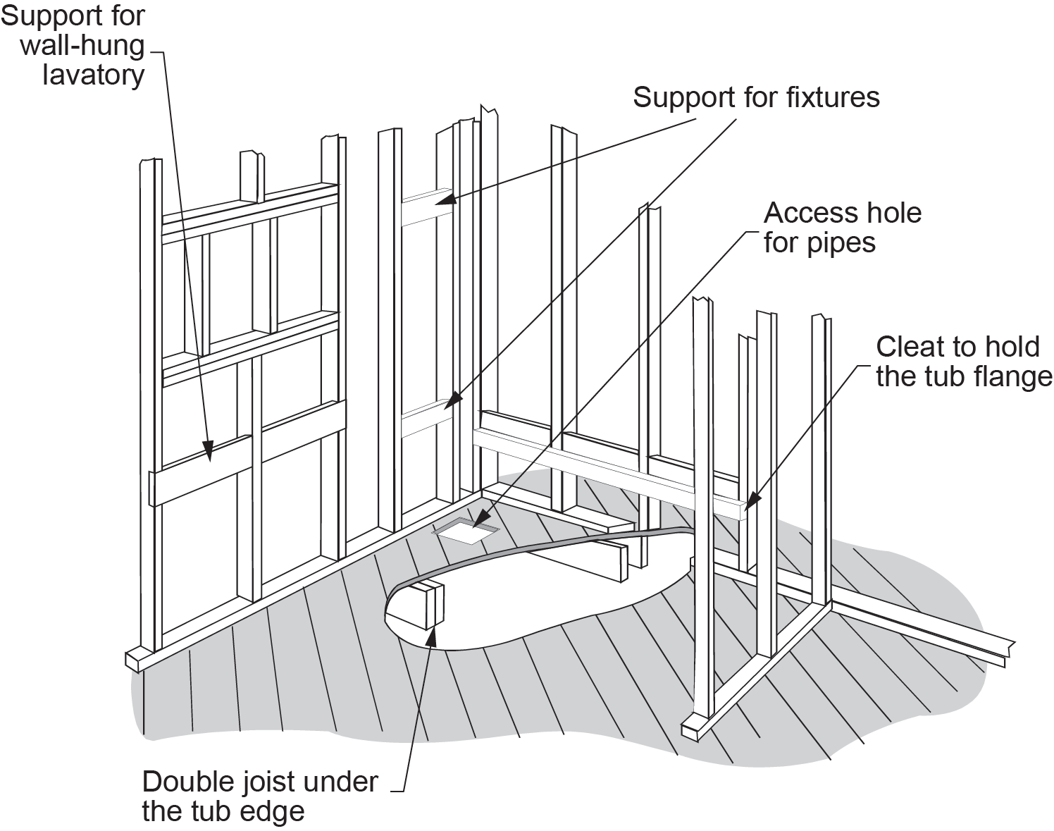
Recessed bathtubs also require supports to hold the rear lip of the tub. If horizontal backing boards are used, perpendicular support legs are required. Otherwise, vertical support pieces can be cut and nailed to studs along the entire length of the back of the tub.
For fixtures that require the additional support provided by carriers, the main support legs are installed behind the finished wall and bolted to the floor and wall studs. The accurate measurement and location of these hidden support legs and the short connectors that protrude through the finished wall are critical. The fixture is held by two pipes or arms inserted into precast passageways inside the fixture. If the carrier legs have not been roughed in correctly, the wall will have to be cut open.
Fixtures must be connected to supply and drainage piping when installing them. These connections must be located to meet the installation requirements of the manufacturer and those outlined in plumbing codes.
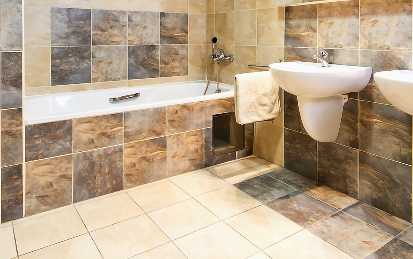
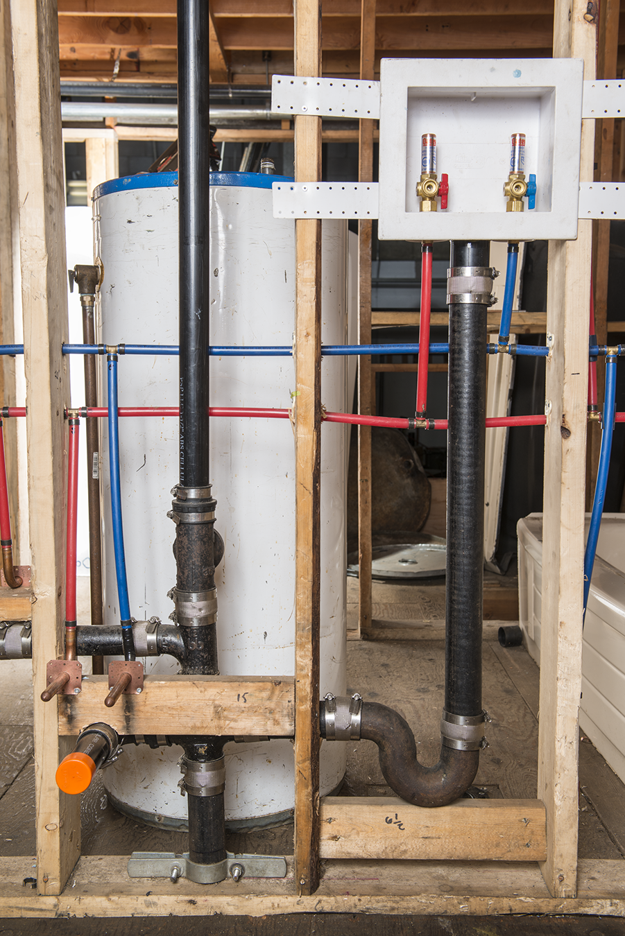
The piping and valves that make up standard tub and shower or stand-alone shower installations are set into the wall before finishing. When provided, access may be from beneath the floor, built into the supporting wall, or in the wall of the next room or hall (Figure 2).
The tub-filler valve (used to blend hot and cold water, the supply lines, and the spouts for shower or tub) must be positioned correctly and mounted securely. The wing-back fitting that supports the shower head must be anchored securely. This fitting, sometimes called a drop-ear, should be a [latex]\tfrac{1}{2}[/latex] in. (13 mm) female iron pipe thread (FIP). A short, reusable nipple is threaded into this fitting and protrudes through the finished wall until the shower is actually installed. At that time, it is replaced with the chromed shower spout or trim nipple, a finishing flange (escutcheon), and a shower head.
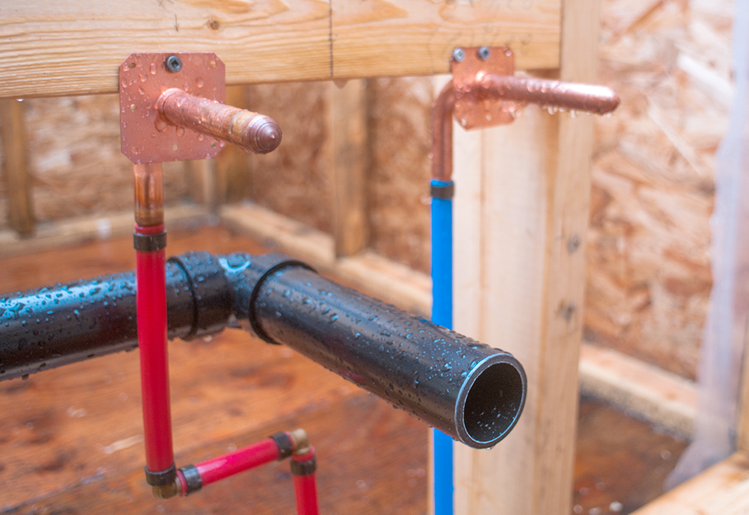
Typical bathtubs have tub-filler valves with integral stops connected to the supply lines (Figure 3). The stops may provide for a solder-type joint with the supply line or be equipped with unions that have threaded, crimped, or solder-type joints. Bathtubs with showers use combination tub fillers that have a diverter valve and integral stops to connect to supply piping. Always provide access so that maintenance can be carried out on diverters or other valves behind finished walls.

NPS [latex]1\tfrac{1}{2}[/latex] in. (38 mm) waste and overflow fittings are used to connect the bathtub to the trap. The drain of a bathtub must fit into a slot in the subfloor that is normally about 150 mm by 300 mm (6 in. by 12 in.).
When installing oversized bathtubs, whirlpools, and soaker tubs, have the fixtures on site at the rough-in stage to ensure accurate rough-in work. Always protect the finish of the fixtures from damage.
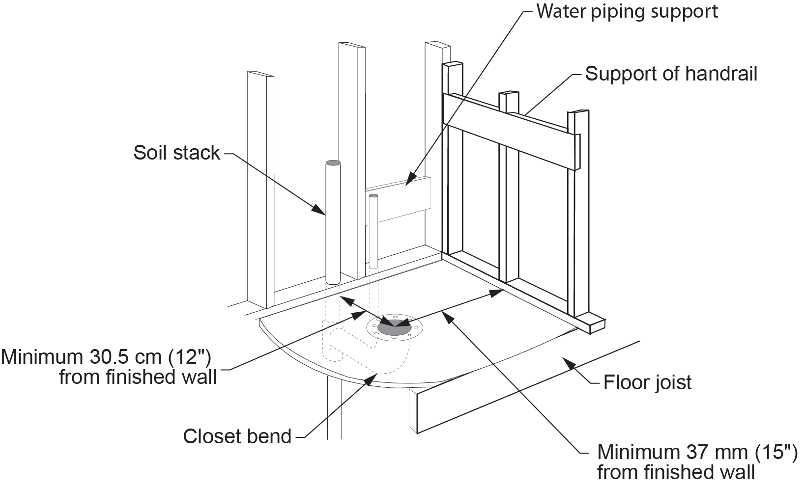
Lavatory water piping and fixture backing should be provided, as shown in Figure 4. Rough in the supports to meet manufacturers’ recommendations and code requirements. Faucets on laundry sinks may be deck-mounted on the vertical backsplash. Water supply lines are connected in the same way as kitchen sinks.
The stop for a water closet is generally a [latex]\tfrac{3}{8}[/latex] in. (9.5 mm) flexible supply. The stop is mounted 150 mm (6 in.) to the left of the centreline of the water closet and is usually 150 mm (6 in.) above the finished floor. Always check the manufacturer’s installation procedures and site specifications to locate correct rough-in dimensions.
A lead closet bend or elbow fitting connects the closet flange to the waste piping (Figure 5). The floor flange should be installed so that it is 30 cm (12 in.) from the finished back wall or according to site requirements. Be sure to double check this dimension for accuracy. Side clearance is often 37 cm (15 in.) minimum from the side wall to the centre of the flange. Ensure that backing boards are installed if grab bars or hand rails are to be installed.
Rough-in connections for a standard dishwasher are not usually complex. The drain from the dishwasher is connected to a wye fitting connected to the sink fixture outlet pipe upstream of the P-trap. A separate supply stop for the hot water supply connection to the dishwasher is usually installed, or it will originate from the sink’s hot water supply.
Clothes washers must be connected to hot- and cold-water supply lines. Separate hot- and cold-water stops are installed 1.2 m (48 in.) from the floor so that they are higher than the back of a standard washer and more easily accessible.
Washing machines require a 5 cm (2 in.) P-trap and a minimum 600 mm (24 in.) standpipe. A standpipe is a vertical section of pipe that extends above the trap weir and must terminate above the flood level rim of the clothes washer. The drain hose from the washer empties into the top of the standpipe during the washer discharge cycle. Laundry boxes (Figure 6) can simplify the installation and provide a neat appearance.
Code Requirements for Fixture Rough-in
Plumbing codes govern the way in which piping, fittings, and fixtures can be installed and the type and placement of fixtures that a plumber may install. Codes also govern minimum sizes of piping, outline requirements for support, and provide a framework of acceptable solutions to the installation of plumbing systems. Plumbers must be familiar with the codes and specifications for each job.
A plumber may have to drill holes, notch, or cut into studs and joists in order to make connections to supply lines or drainage, waste, and vent lines. At times, access holes may have to be cut through firewalls or fire separations to allow supply or drainage piping to pass through. When a rough-in for fixture installation affects a building’s structure, provincial or national building code requirements define minimum requirements. Engineered building materials state their own installation specifications.
While there are some common guidelines to follow when carrying out the rough-in and installation of fixtures, always check local building and plumbing codes and your provincial codes to meet minimum compliance.
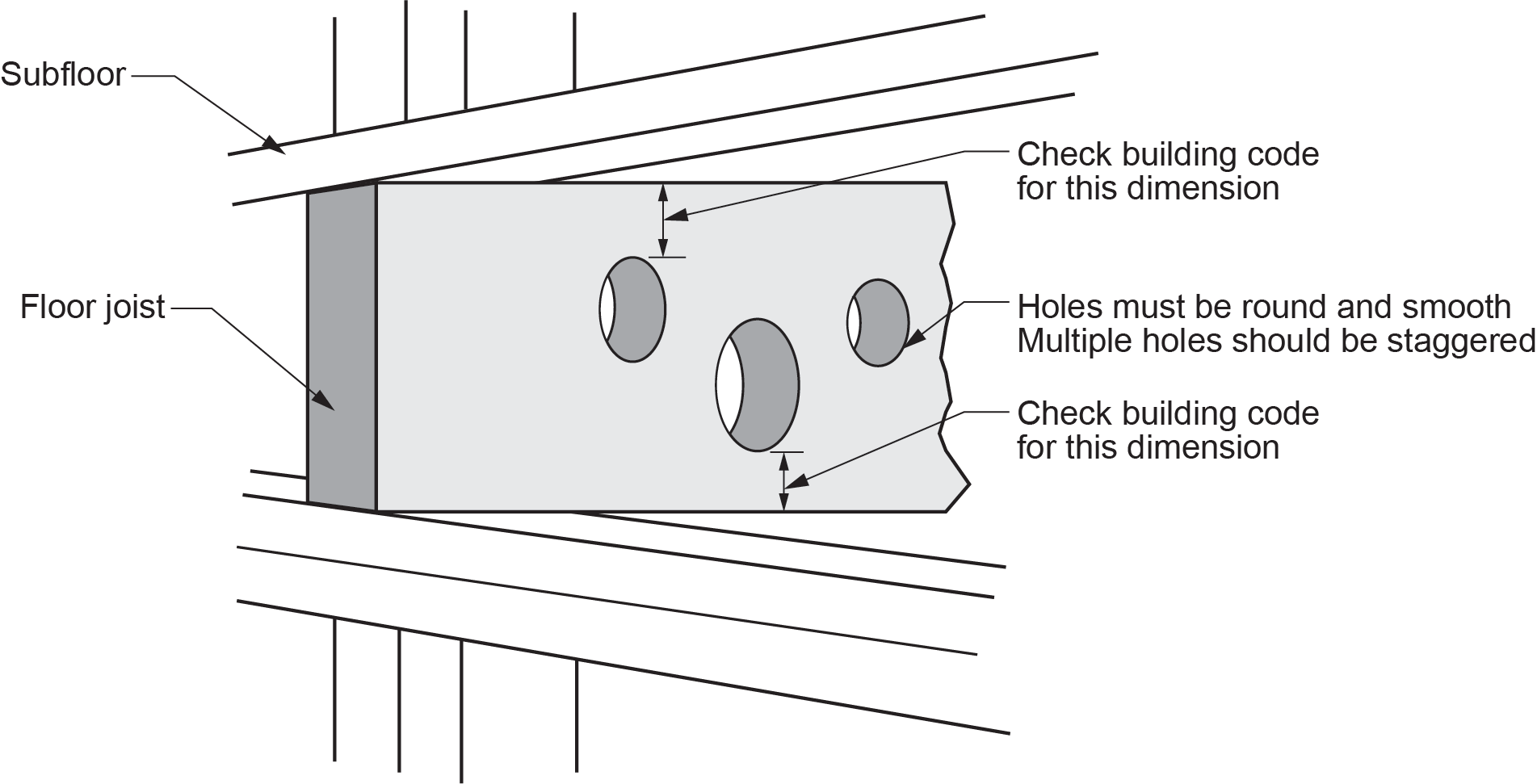
Requirements pertaining to cutting, drilling, or notching support members ensure that the installation of piping and fittings does not weaken the structure. Building code requirements generally state that holes cannot be larger than one-quarter of the depth of a member and no closer than 50 mm (2 in.) from the edges (Figure 7). Notches on horizontal members must always be on the top, within half the joist’s depth from the edge of the bearing and not deeper than one-third of the the joist’s depth.
Before notching or drilling studs, always check to see if it will affect a load-bearing stud. If a stud is load-bearing, cutting or notching should not affect more than one-third of the stud’s depth (roughly 33 mm/1 in. if the stud is a 2 by 4). If the stud is not load-bearing, cutting or drilling can take place within 40 mm ([latex]1\tfrac{1}{2}[/latex] in.) of the stud’s depth. If these guidelines are exceeded so as to weaken studs, the studs must be reinforced in an acceptable way.
In some cases, piping must be carried through firewalls or fire separation in floors. There are specific code requirements that govern the treatment of piping that travels through fire-resistance-rated areas. Any piping that penetrates a firewall or fire separation must be sealed so that the wall or floor retains its fire stop rating. Fire stop ratings are a classification system that relates to the amount of time a barrier will hold back fire. Piping must be non-combustible or fire-rated thermoplastic piping. Combustible piping requires a fire-stopping system that seals the penetration when the piping melts due to exposure to high temperatures. Metallic piping can have a tendency to transmit heat from fire, so additional considerations may be required.
Fixtures should be located in the bathroom to make their usage comfortable and to not restrict movement. Plumbers should ensure that there is 530 mm (21 in.) clearance between the front of a tub, shower stall, or lavatory and the opposite wall. If another fixture is directly in front of the tub, shower, or lavatory, 450 mm (18 in.) clearance is recommended. Water closets should have 450 mm (18 in.) clearance between it and an opposite wall or fixture and a side clearance of 370 mm (15 in.).
Information Sources
Roughing in plumbing for fixtures is a process that requires accurate information about the:
- Location of existing supply lines and drainage
- Waste and vent lines
- Number and type of different fixtures
- Overall dimensions of a building
Different jobs will have varying amounts of information readily available; plumbers must know how to look for the information they need.
The range of information available to you when you begin a plumbing project depends on the size of the job. On small, single-family dwelling projects, there may be no information beyond an architectural and mechanical drawing and a list of specifications that includes a description of the type and number of fixtures required. Many small projects will have even fewer details available and will require that the plumber make suggestions as to the type and style of fixtures. Plumbers who deal extensively with this type of project should have a catalogue that contains a range of product specification sheets from different manufacturers. In this case, each manufacturer would provide the detailed rough-in information needed, and the plumber would decide on the arrangement of fixtures and the specific location of each one.
For more extensive projects, the plumber may be handed a number of different drawings that provide important information to guide roughing-in. You may only be provided with a set of working drawings when you begin a plumbing project. If piping layout drawings have not been prepared, you will have to gather information from different types of drawings. Large projects may supply:
- Architectural drawings
- Structural drawings
- Mechanical drawings
- Electrical drawings
Architectural drawings are the first source of information for rough-in within a building. They provide the dimensions for each room and identify the arrangement of fixtures. For medium to small-size projects, the architectural drawings contain information about materials, floor plans, and elevations and show details, such as location of drains and exterior hose bibbs and hot and cold water supply lines. Larger projects may have so much information that it cannot fit on one drawing, and separate floor plans or elevation plans may be required.
Structural drawings also help you plan how piping can travel within walls. These drawings identify load-bearing members. Remember that building codes prohibit cutting, notching, or drilling studs and joists in a way that would weaken the structure.
Mechanical drawings show where the supply piping (hot and cold water), drainage, waste, and vent lines travel. The architectural details are removed so that it is easier to see where the rough-in connections for fixtures should be made.
Electrical drawings show the location of all electrical lines and outlets. This information helps ensure that the planned path for piping and fittings does not interfere with electrical lines.
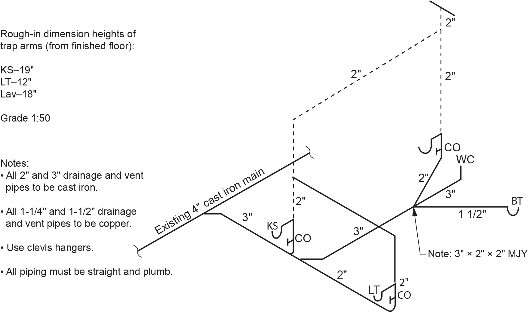
These drawings all provide pieces of information that are critical to accurate rough-in work. However, the plumber may also require more detailed information about the type and size of piping and fittings and how they will travel throughout the structure. An isometric or piping layout drawing may be available, or the plumber will have to prepare one from the information supplied by the architect. Piping isometric drawings, as shown in Figure 8, also show the connections between piping, the path of travel (both inside the wall and under the finished floor), and where piping will connect to fixtures.
A piping layout drawing provides more detailed information, including piping lengths and exact fitting placements. This information will allow you to create a materials list before rough-in work is done.
Before a complete materials list can be done, you must also calculate the exact location of fixtures and the way they will connect to the supply and DWV piping that travels within the walls. One of the most important sources of information are the rough-in and product specification sheets available from the manufacturer.
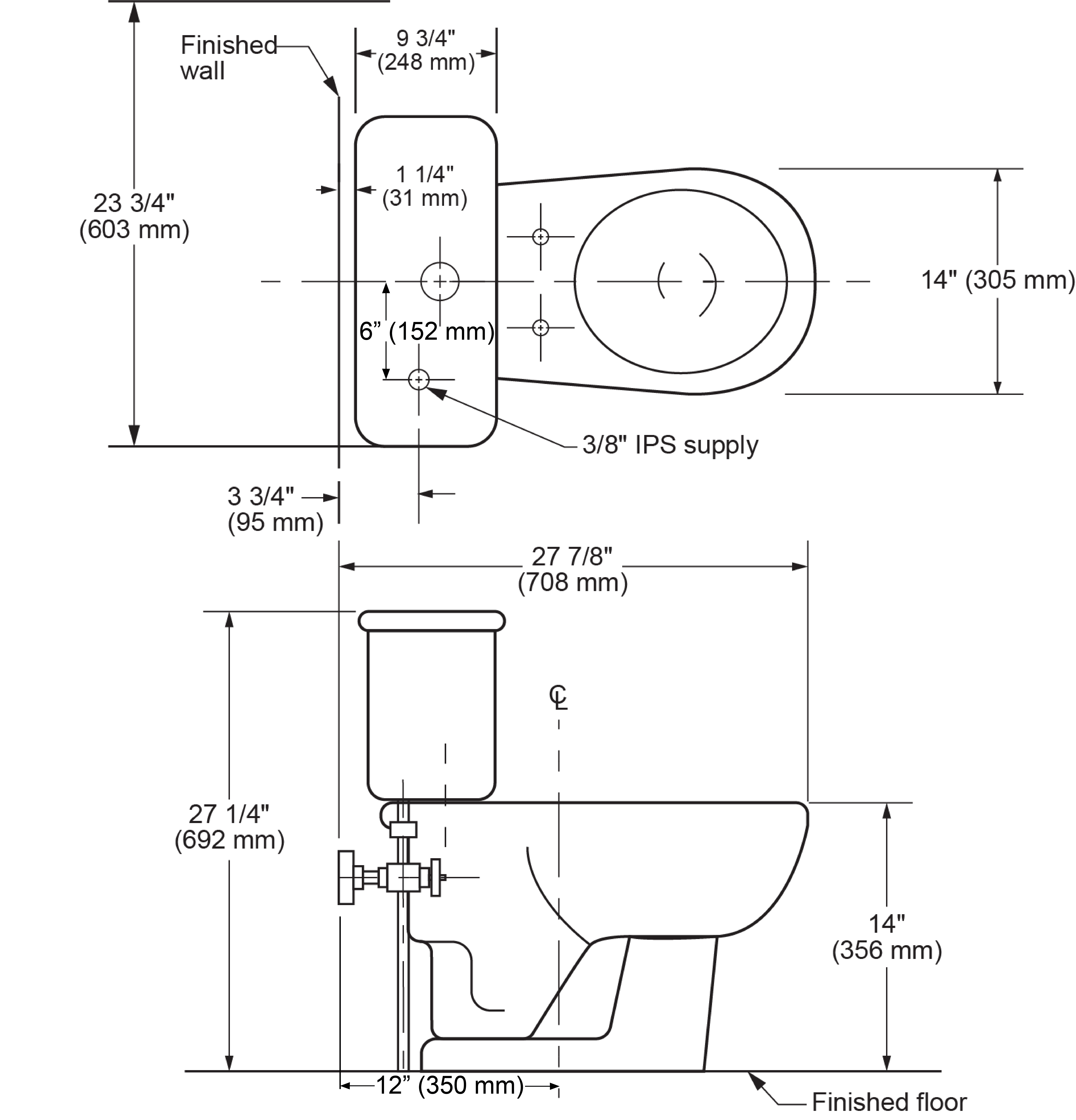
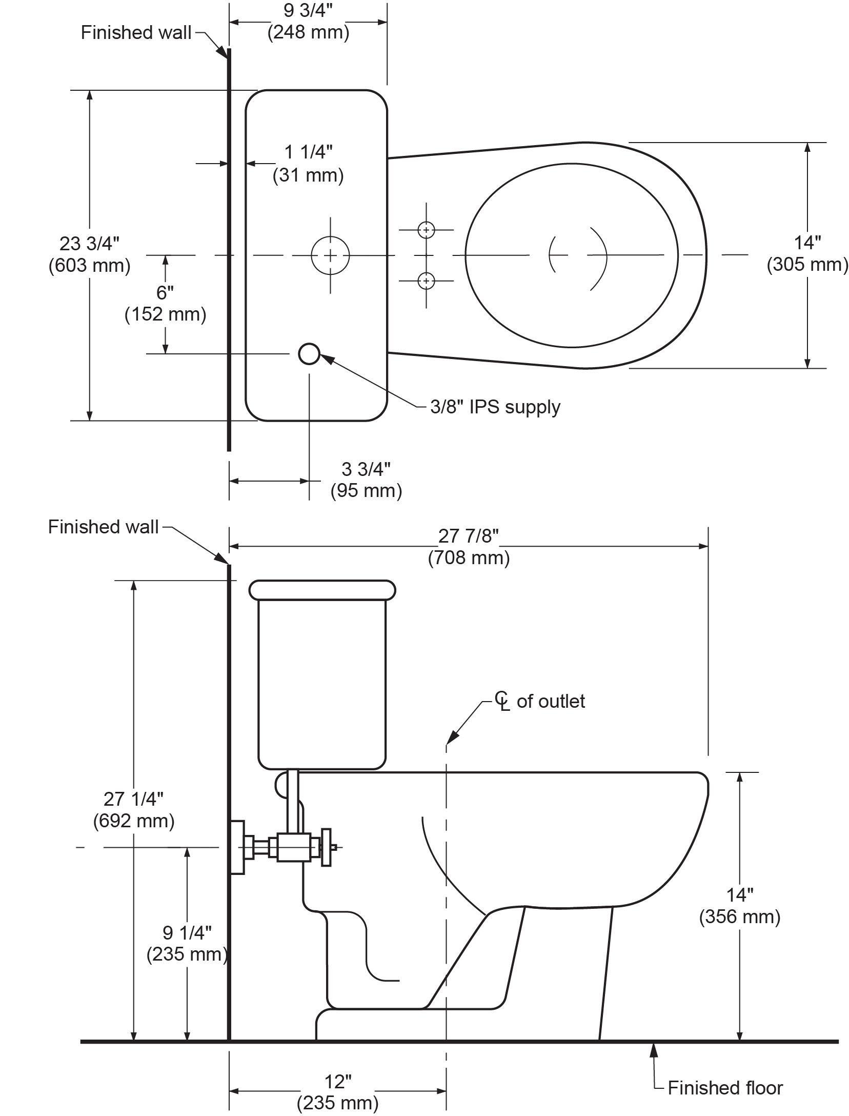
Rough-in documents contain all the rough-in information required to install a range of fixtures. Figure 9 shows rough-in specifications for a standard water closet. Notice that the plan view and front elevation provide the dimensions necessary to install the closet flange and ensure that the water supply line protrudes through the wall at the correct height and horizontal position. These dimensions are common for most standard styles of water closets; the centreline of the closet flange is approximately 305 mm (12 in.) from the finished wall, and the supply line is located 152 mm (6 in.) to the left of the centreline of the flange.
Never assume that you know the dimensions for rough-in; always refer to the manufacturer’s rough-in information because the details may vary slightly for the style of fixture you are installing. Even minor differences in the location of supply connections or drains can result in time-consuming and expensive alterations when installing fixtures.
Figure 10 provides another example of rough-in details available from fixture manufacturers. This wall-hung lavatory is shown in a top view and a front view to illustrate the overall dimensions of the fixture and the exact locations for drain and supply line connections. This sheet also warns of a minor variation in measurement accuracy of plus or minus 7 mm ([latex]\tfrac{1}{4}[/latex] in.). The plumber must be aware that no published measurements can be exactly accurate, as there will be minor differences in size created during the manufacturing process.
In installations where tolerances are narrow, measure the fixture before rough-in to confirm the dimensions on the rough-in documentation.
The wall-hung lavatory in Figure 10 is a model supported by metal arms concealed in the sides of the fixture. This requires the rough-in of carrier supports attached to studs in the wall. The measurement and actual installation of these supports is very important because they must match up to the precast holes in the lavatory. Any error in the measurement and rough-in might mean that the wall would have to be cut open to re-position the supports.
Most rough-in documents from manufacturers provide dimensions measured from the finished floor or walls. The plumber must find out how the walls or floors will be finished so that the difference in dimensions from the subfloor or unfinished wall can be added to actual calculations. For example, a rough-in sheet for a water closet may show the centreline of the drain to be 305 mm (12 in.) from the wall, but the plumber will be roughing in the drain piping when the wall and floor are both unfinished. Therefore, when measuring from the wall behind the floor flange, the thickness of the finished wall must be added. For standard drywall, add 12.7 mm ([latex]\tfrac{1}{2}[/latex] in.). The drain would be located 318 mm ([latex]\tfrac{125}{8}[/latex] in.) from the wall studs.
Not all rough-in sheets show the location or size of backing required for fixtures. The plumber may have to measure the fixture and the distance between wall studs to determine how to size and install backing. Backing requirements for installing fixtures for people with disabilities are usually detailed in building codes, the owner’s requirements, and manufacturer’s specifications.
Minimum clearances between fixtures and walls are another measurement that the plumber must make before they can complete rough-in work. In the past, the plumbing code regulated the minimum fixture clearances for residential bathrooms. Currently, the only clearance requirements are contained in the building code for accessible washrooms.
Procedures for Finding Rough-in Information
The procedures you follow to collect rough-in information will vary depending on whether you are roughing in supply piping and drainage or waste and vent lines, or doing rough-in for fixture connections. Another factor that will influence the steps you follow is what information you receive when you start a job. Assuming that you are roughing in fixtures on a medium-sized project, complete with project drawings described above, you would do the following:
- Read the architectural drawing. Make a note of the finish planned for the walls and floors (to estimate finished thicknesses). Look for the number of fixtures planned and their approximate locations, and check if the model and manufacturer of each fixture are identified.
- Read the mechanical drawing. Look for the path of travel of important supply and DWV piping. If no piping layout or isometric drawings are available, sketch one and mark on it the connections required for fixtures.
- Review the electrical and structural drawings. Make sure the planned piping connections will not interfere with electrical lines or outlets or require you to weaken supporting members.
- Locate a manufacturer’s rough-in documentation or individual rough-in sheets for the fixtures identified in the architect’s information. Check the important dimensions for pipe connections and fixture supports. Measure at the intended installation location to confirm the actual location of connections and that clearances are adequate.

Fixtures are expensive and are not intended to be handled frequently. Take the time to check and verify rough-in dimensions so that you will not have to install and remove fixtures more than absolutely necessary. With accurate measurements, you can avoid breakage or damage to expensive fixtures.
- Refer to relevant code requirements for rough-in work. Check that your planned piping connections and fixture supports will not conflict with any regulations.
Check with your local plumbing inspector for any special requirements for rough-in inspections. The Authority Having Jurisdiction (AHJ) has the final word regarding the acceptance of plumbing fixture installations.
As a plumber, you are responsible for ensuring that the backing for each fixture provides adequate support (Figure 11). Even when other tradespeople install this backing, you must verify their work and ensure that the backing will support the fixture you plan to install. You are ultimately responsible for this.
Installing Bathroom Fixtures
Most bathrooms have at least three fixtures: a lavatory, a bathtub and/or shower, and a water closet. The arrangement of these fixtures and the style and colour of each are decided by the owner and/or architect. Architects first visualize what they want to achieve; they decide what the bathroom should look like to suit the owner’s needs and personal tastes. From this visualized design, architects prepare detailed drawings that other tradespeople use to actually construct the finished bathroom.
For example, if an architect decides that the lavatory should be placed 1 m (3 ft) from the far wall of a bathroom, this could affect three tradespeople. The carpenter may need the location and dimensions of the fixture to prepare a recessed area for the medicine chest. The electrician would use the same information to determine where to place wiring and outlets. The plumber must connect to water supply lines and make sure that drain and vent connections are appropriately placed.
A plumber will consult blueprints and rough-in drawings or specifications from fixture manufacturers to determine the supports that each fixture will need and where connections to supply and waste lines should be located. Rough-in drawings will also show the important dimensions that the plumber uses to install supports in the necessary locations.
Installing Lavatories
There are two basic types of lavatories or basins: wall-hung or countertop.
To install a standard wall-hung lavatory, a plumber must determine the placement of water supplies and waste connections. Wall-hung units require backing (installed by the carpenter or plumber) to provide adequate support for the lavatory’s mounting bracket. Figure 12 shows a sample rough-in sheet for a wall-hung lavatory.
Centrelines are one of the most important pieces of information in rough-in documentation. They provide a reference point for determining the location of piping and supports. The centreline of the fixture in Figure 12 is clearly indicated.
Two known reference points must be used to locate a point. The second reference point, shown on a rough-in sheet, is the distance above the floor or from the wall. The rough-in information should identify whether the measurements are from the finished floor or wall. Rough-in sheets generally provide two views: a top view and a front view; a side view and a front view; or a back view and a top view. These different views will show the plumber the important dimensions. When fixtures require additional supports, such as carrier arms inserted into the sides of a lavatory, a third view or side view may also be provided on the rough-in sheet.
Figure 12 shows a plan view and front elevation view. The waste piping, with a minimum [latex]1\tfrac{1}{4}[/latex] in. (32 mm) diameter, and its position at 432 mm (17 in.) above the finished floor are clearly indicated. The water supply lines are shown at a distance of 546 mm ([latex]21\tfrac{1}{2}[/latex] in.) above the finished floor.
Wall-hung lavatories are supported by different styles of metal brackets or supports bolted to the finished wall. A wooden backing is installed by bolting it to studs inside the wall. Heavy, long screws are used to attach the fixture support brackets through the finished wall to the backing boards. The board must be large enough to accept the support bracket screws and the screws used to secure the fixture. The rough-in sheets should show the location of all fastening screws. They prevent the lavatory from being easily lifted off the supporting bracket after final installation.
When wall-hung lavatories are designed for use by people in wheelchairs, they generally require arm carriers securely bolted to support plates installed in the wall. Figure 13 shows a typical support for plates, the carrier arms, and the rough-in details of the lavatory. The plates must be precisely aligned or the carrier arms will not fit into the holes cast into the sides of the lavatory.
All measurements for installing hangers and backing for lavatories should be done carefully. Most lavatories are manufactured from vitreous china and are very expensive. They are not designed to be lifted on and off supporting brackets frequently; if handled too frequently or roughly, they will break or crack. Careful attention to measurements and installation of supporting brackets and backing will ensure that expensive fixtures do not have to be replaced.
If you are installing a countertop basin, a carpenter will likely install the countertop. The countertop must be mounted at the correct height and attached securely to backing in the wall or supported by a floor-mounted cabinet. Some countertops are precut for the fixture; others must be cut to fit the basin. The manufacturer may supply the template, or the plumber or carpenter may have to trace the contours of the actual fixture. To trace a basin, place it upside down on the countertop and draw a line around its perimeter. Remove the basin and draw a second line at a specified distance inside the first line, usually about 13 mm ([latex]\tfrac{1}{2}[/latex] in.). This ensures that the basin will rest on a lip of the countertop. The cut is made on the inside line.
Water supply stubs should have the caps removed, and the pipe should be cut to the desired distance from the finished wall. Most bathroom basins use angle stops screwed onto the supply stub or connected with a compression fitting with a hexagonal nut and ferrule. The supply lines from the angle stops to the faucets are connected after the basin is installed.
Faucet assemblies come in many different configurations. Most can be adapted to fit the basin design.
Installing Faucets
You may install faucet fittings and pop-up drain assemblies before or after hanging the basin on wall supports or placing it in the countertop. Some plumbers find it easier to do as much pre-assembly as possible to reduce the amount of work that must be done underneath the basin or in a confined space. They hang the basin with the trim installed and hook up the water-supply tubing and drain piping last.
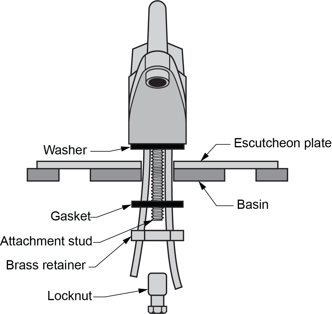
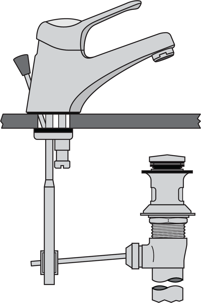
Manufacturers supply detailed installation instructions for each style of faucet. The following steps outline a general procedure to install a common model, single-handled, centre-set basin faucet (Figure 14):
- Place the gasket under the faucet body. Turn the faucet over and align it with the holes in the basin. Clean off any excess putty.
- Insert the faucet supply tubes and threaded attachment stud through the hole in the basin. Make sure that the gasket is properly seated and that the lift rod for the pop-up drain assembly is in place and operating freely.
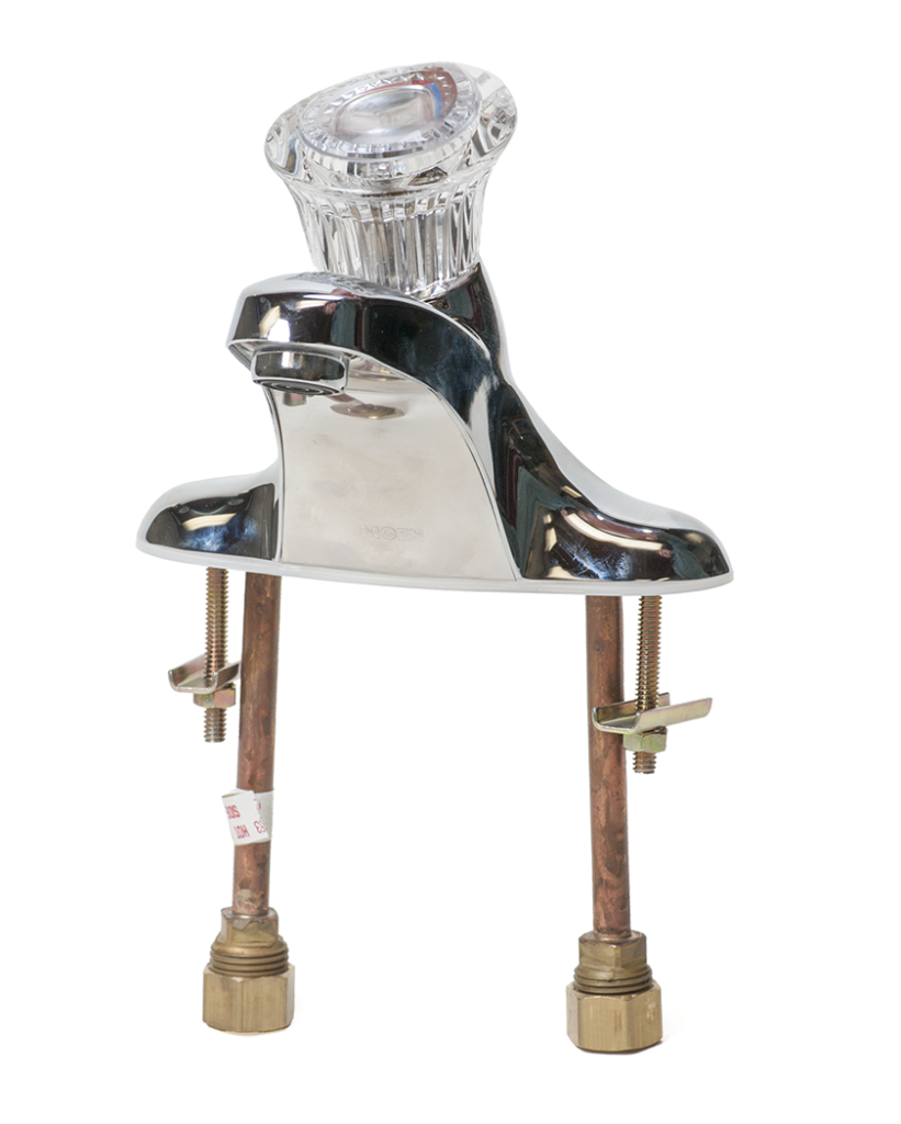
Figure 14 Faucet body, supply tubes and attachment studs. (Skilled Trades BC, 2021) Used with permission. - From the underside of the basin, place the retainers (or washers) on the attachment studs until they meet the basin. Thread the locknut onto the attachment stud and tighten it by hand until it holds the faucet firmly in place.
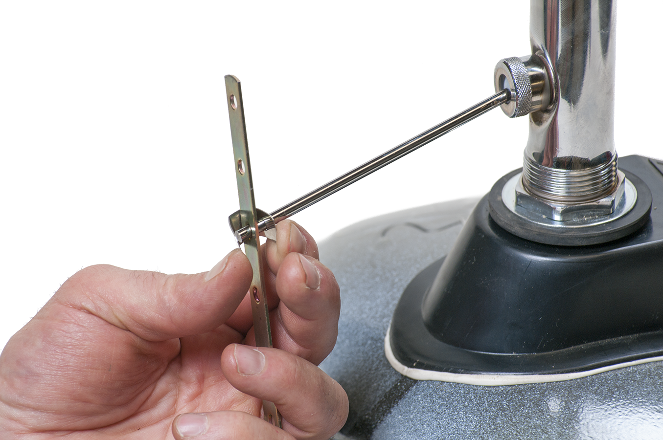
- Holding the inlet tubing out of the way, use a wrench to tighten the locknut completely (Figure 15). The water supply tubing will be connected later.

Figure 15 Secure fitting to basin with locknut. (Skilled Trades BC, 2021) Used with permission.

Installing Pop-Up Drain Assemblies
The following procedure describes the basic steps to install a mechanical pop-up assembly supplied with the faucet fitting described above. Always follow manufacturer’s directions for the type of faucet and pop-up plug assembly you are installing.
- Apply a bead of plumber’s putty or silicone sealant under the edge of the drain plug flange (Figure 16). Insert the drain plug fitting into the drain hole in the basin.
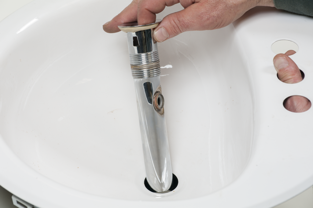
Figure 16 Insert drain plug fitting. (Skilled Trades BC, 2021) Used with permission. - Hold the drain plug fitting firmly in place with one hand. With the other hand, place the gasket, washer, and locknut onto the threaded end of the plug. Tighten the locknut firmly by hand (Figure 17).
- Turn the drain plug until the pivot rod of the mechanical coupling is pointing toward the back of the basin. Tighten the locknut completely. You may use a large hexagon wrench, spud wrench, or adjustable wrench. Never use a pipe wrench to tighten the locknut because it may mark the surface of the fixture. Be careful not to overtighten, as this can chip or break the fixture.

Figure 17 Install lower gasket, washer and locknut. (Skilled Trades BC, 2021) Used with permission. - Clean any excess putty that has been squeezed out from under the plug. Drop the stopper into the drain plug opening. Tighten the bushing on the mechanical coupling (Figure 18) until the pivot rod is snug but movable. Depending on the outlet fitting design, there may be additional teflon washers required on either side of the ball to help it seal.
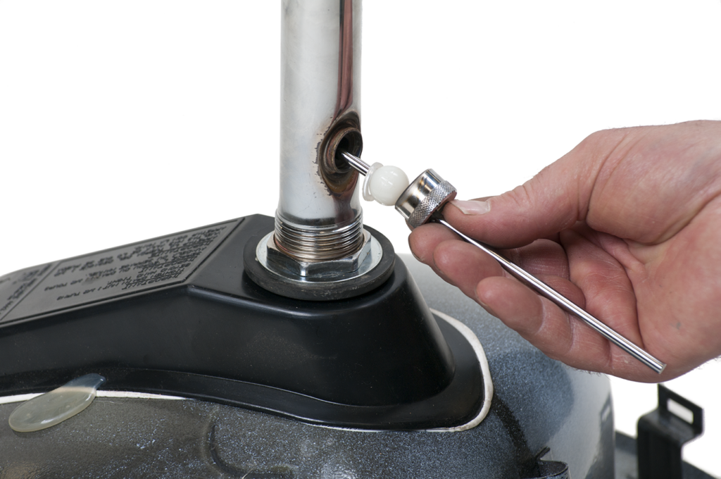
Figure 18 Install pivot rod. (Skilled Trades BC, 2021) Used with permission. - Clip the pivot rod to the perforated extension rod in the hole closest to the end of the pivot rod. Squeeze the clip gently; make sure that the clip slides easily onto the rod (Figure 19).
- Move the pivot rod so the stopper/plug is in the open position; the horizontal rod should point down wards (away from the basin top).
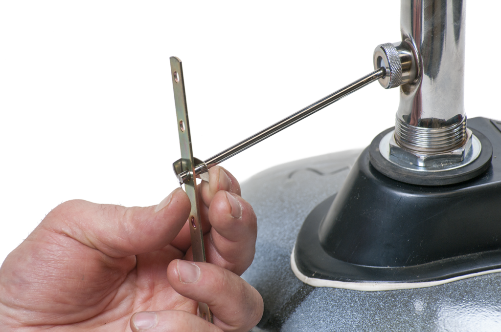
Figure 19 Squeeze clip gently. (Skilled Trades BC, 2021) Used with permission. - Adjust the lift rod so that the stopper operates smoothly. When the lift rod is pushed down to the surface of the fitting, the stopper should be fully open. Pulling the lift rod to its furthest upward position should cause the stopper to seat tightly in the basin drain hole.
- After the pop-up assembly has been installed, the final drain connection can be made.


Securing the Basin
Depending on the method you choose for installation, you may now have to secure the basin before making the final water supply and drainage connections.
For a wall-hung basin, slip the basin gently onto the hanger. Check that the basin is level and positioned correctly in relation to the supply and drain connections. When you are sure that the position is accurate, secure the basin to the wall using the holes cast into the bottom of the fixture.
If the basin is a pedestal style, connect water supply and drain piping, then slide the pedestal into place gently. It should fit the contours of the bottom of the basin exactly and hide the trap, drain, and supply piping. Seal the seam between the basin and pedestal with silicone.
For a countertop basin, slip the basin gently into the prepared opening. If the basin is an old style with a metal rim, run a bead of plumber’s putty under the rim to seal the ring to the countertop. Some basins are clamped to the countertop with hidden screws.
Plumber’s putty should not be used to seal trim to countertops or basins made of synthetic marble because it causes staining. When working with synthetic marble, use silicone caulking to seal joints and seams.
Some countertop basins are “self-rimming,” which means that they are supplied with a rubber gasket under the rim of the basin and do not require the use of silicone. The gasket has an extra strip that protrudes beyond the edge of the basin that helps hold the gasket on until the basin is installed. After you have installed the basin, peel away this extra strip to leave a clean, professional finish.
Making Final Connections and Testing
- Gently bend supply tubes or flexible hoses from the faucet fitting to meet the supply stops. Usually supply tubing is attached to the supply stops with compression fittings. Supply tubes use a compression nut and ferrule supplied with the stop, whereas the flexible hoses come complete with a connection nut and internal rubber washer.
- Make sure you connect the hot water supply to the left inlet tube (when you are facing the basin). Connect the cold water supply to the right inlet tube.
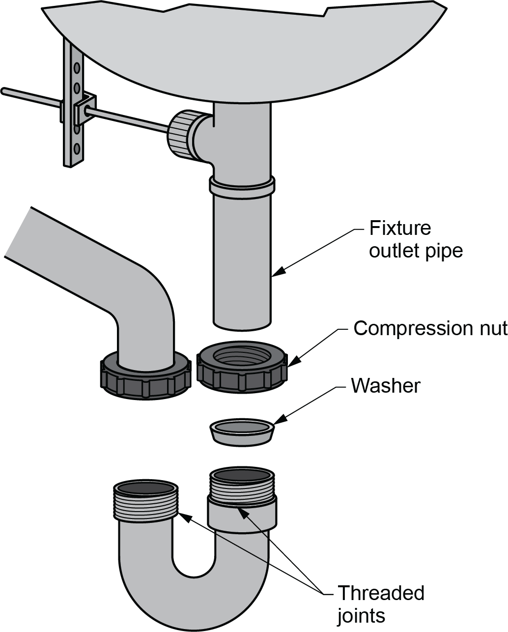
- Connect drainage piping. Insert the threaded end of the fixture outlet pipe into the lower end of the mechanical coupling.
- Connect the lower end of the fixture outlet pipe to the inlet of the basin trap. Most traps are connected with slip-type fittings. Then, connect the trap outlet to a trap arm long enough to connect to the waste pipe stub at the finished wall (Figure 21).
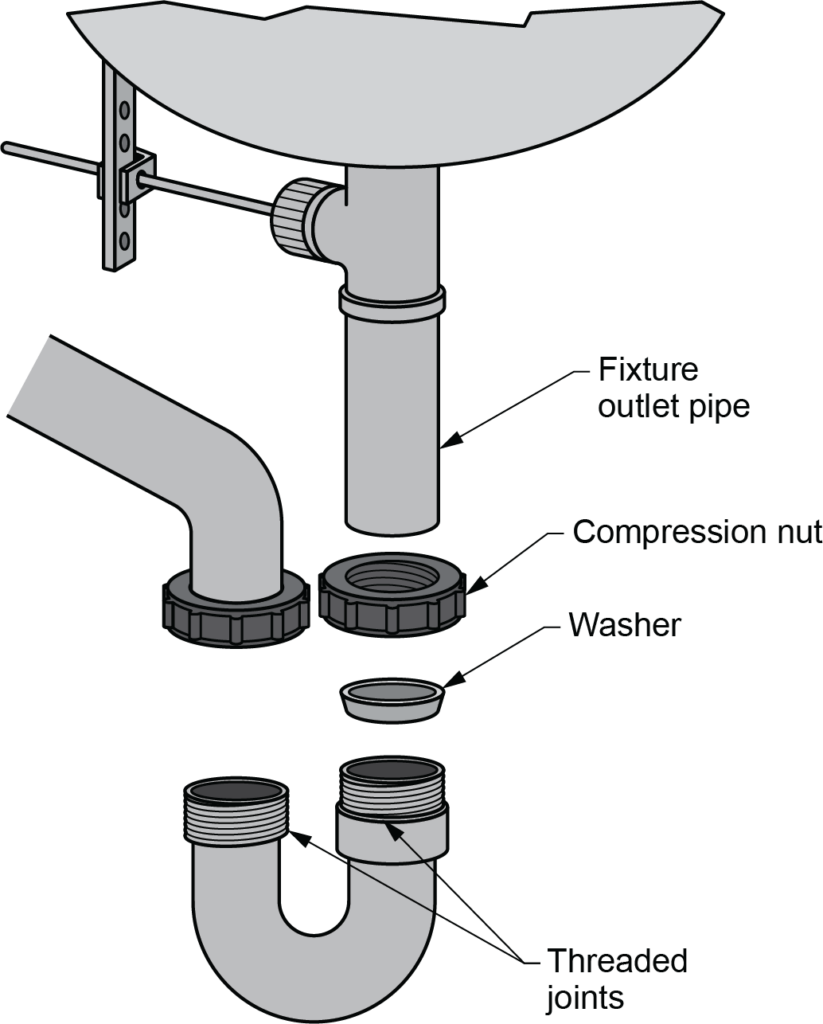
Figure 21 Connected P-trap to drain piping. (Skilled Trades BC, 2021) Used with permission. - Test your connections by moving the faucet control lever to the right and turning on the cold water supply stop. The water flowing from the faucet should be cold. Turn off the cold water supply and move the control to the left. Turn the hot water supply on and check the temperature of the water.
- Ensure that the aerator is in place and turn both stops on. Test the general pressure control and temperature regulation of the faucet mechanism. The spray from the faucet spout should be fine, even, and have adequate pressure.
- When the water is flowing smoothly, plug the basin and let it fill with water to within 50 mm (2 in.) of the flood level rim.
- Turn off the faucets and check for leaks at the supply stops and where supply tubing connects to the faucet under the basin.
- Check that the overflow is draining the sink properly. Make sure the pop-up assembly is working smoothly. Look for leaks in the drainage piping.
Installing Bathtubs and Showers
A standard enamelled steel or fibreglass-skirted bathtub set into a recess in the wall requires supports along the entire back side of the tub (Figure 22). Some manufacturers suggest nailing short blocks of wood to wall studs at the appropriate height to support the lip of the tub. This system helps eliminate any shrinkage between the edge of the tub and the wall tile.

The bathtub is supported by horizontal and vertical members. A horizontal ledge, formed by pieces of stud fastened to wall studs, supports the bathtub and fits the integral clips on the bathtub lip. Measure the height of the horizontal ledge from the subfloor, and the height of the vertical supports from the top of the horizontal ledge to the subfloor. Vertical and horizontal supports must be checked with a level.
Some types of jetted tubs and whirlpool baths require continuous support from a mortar base under the entire bottom of the tub. Manufacturers will supply recommended support specifications, and these must be followed, or the warranty of the fixture will be voided.
Information about the required location of backing and its dimensions is taken from the manufacturer’s rough-in drawings. Most showers require a backing to which the wing back elbow can be secured. This fitting has an iron pipe connection end to which a short nipple is attached while rough-in is completed. When the wallboard is attached and the fixture is installed, the nipple is removed, and a shower arm or faucet spout is screwed in. In larger installations, the architect’s specifications should also be consulted because special fixtures or placement of components may be required.
The drain piping and trap under the floor should be ready for final connections. An access hole large enough to accept the bathtub drain should have been cut in the flooring. Generally, these slots are 150 mm (6 in.) wide by 305 mm (12 in.) long. The 150 mm (6 in.) end will be centred on the centreline of the drainage piping.
Diverter valves, mixing valves, and faucet bodies hidden by the finished wall should be in place. The shower pipe riser, shower arm fitting (drop ear or wing back), and tub spout elbow and nipple connection should be in place. The tub filler and diverter connections inside the wall are most commonly centred in line with the bath waste and overflow.
To install a standard rectangular, right-hand or left-hand outlet recessed bathtub and shower, do the following:
- Check that all rough-in details have been completed and located accurately.
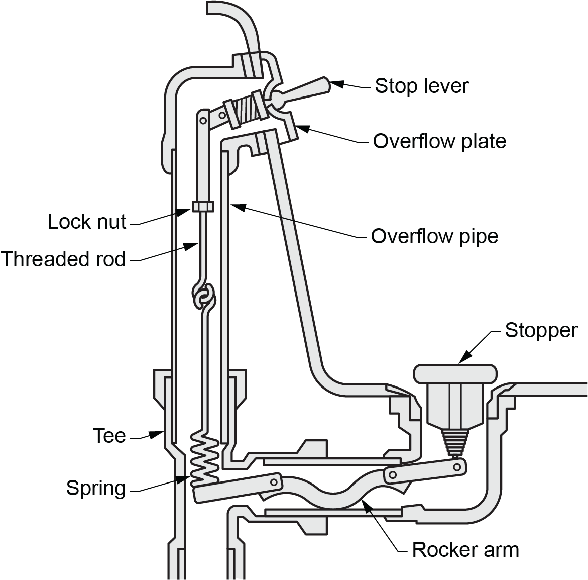
- Connect the overflow and waste assembly (Figure 23) to the tub. Remember to put plumber’s putty or silicone sealant under the drain plug fitting to seal it to the tub drain hole. Also, make sure to check the fit of the overflow gasket onto the back of tub overflow opening. Because of the angle, this fit-up can fail if not aligned properly. Follow the detailed instructions for the type of waste and overflow fitting you are installing.
- Move the tub into position. Slide the tub into place so that the back lip is supported by the horizontal support ledge. Make sure the tabs are hooked behind the horizontal supports and the tub has a minimal slope to the back lip.
- Bathtubs should have a perimeter lip or tiling flange that extends behind the finished wall. This flange should be clipped to studs in the wall. When the wall is finished, the wallboard and tile or acrylic/fibreglass panels will cover the flange.
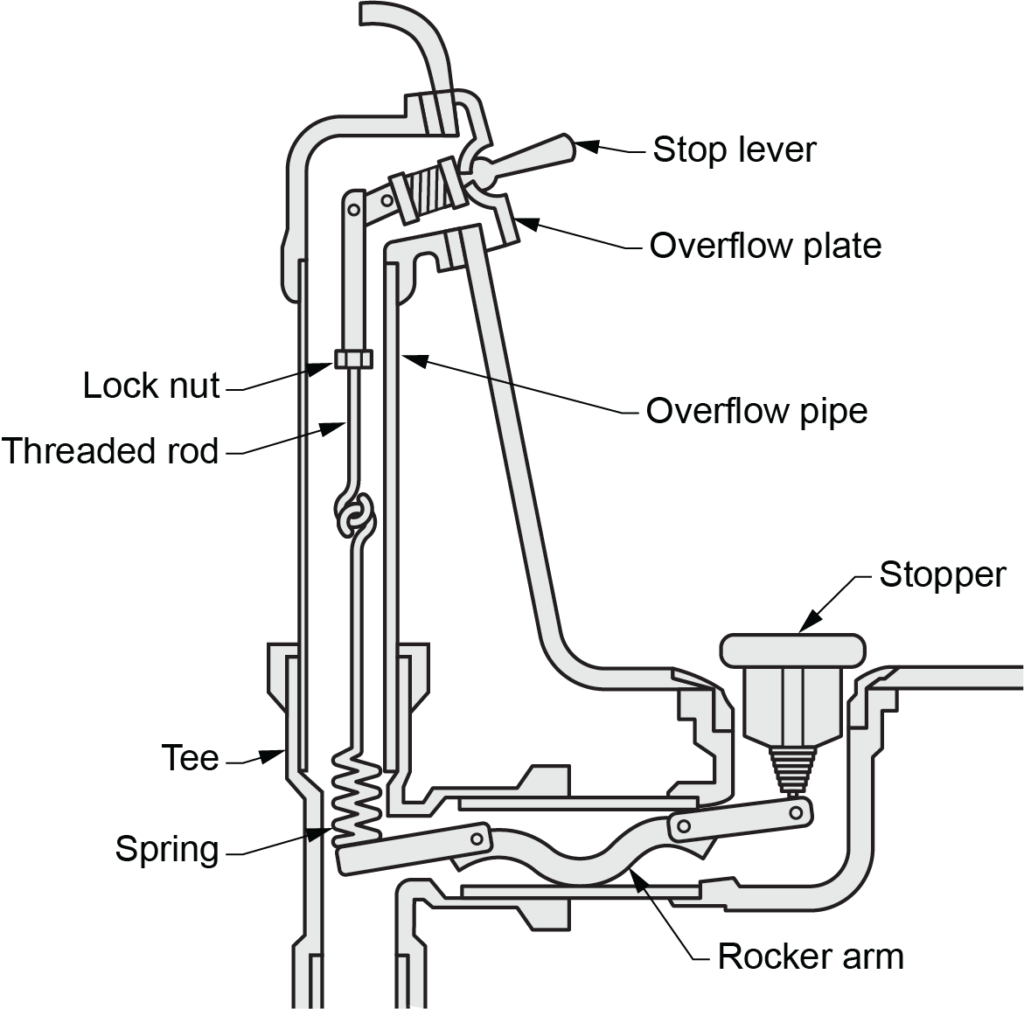
Figure 23 Mechanical waste and overflow assembly. (Skilled Trades BC, 2021) Used with permission. - Attach the bathtub and shower controls, escutcheons and spouts after the final wall finish is applied. Some faucet assembly styles will only have a central control lever and escutcheon, a diverter control, and the shower and tub filler spouts. Other styles will have separate handles for hot and cold water and a central diverter control. Follow the detailed manufacturer’s directions to install all fixture trim.
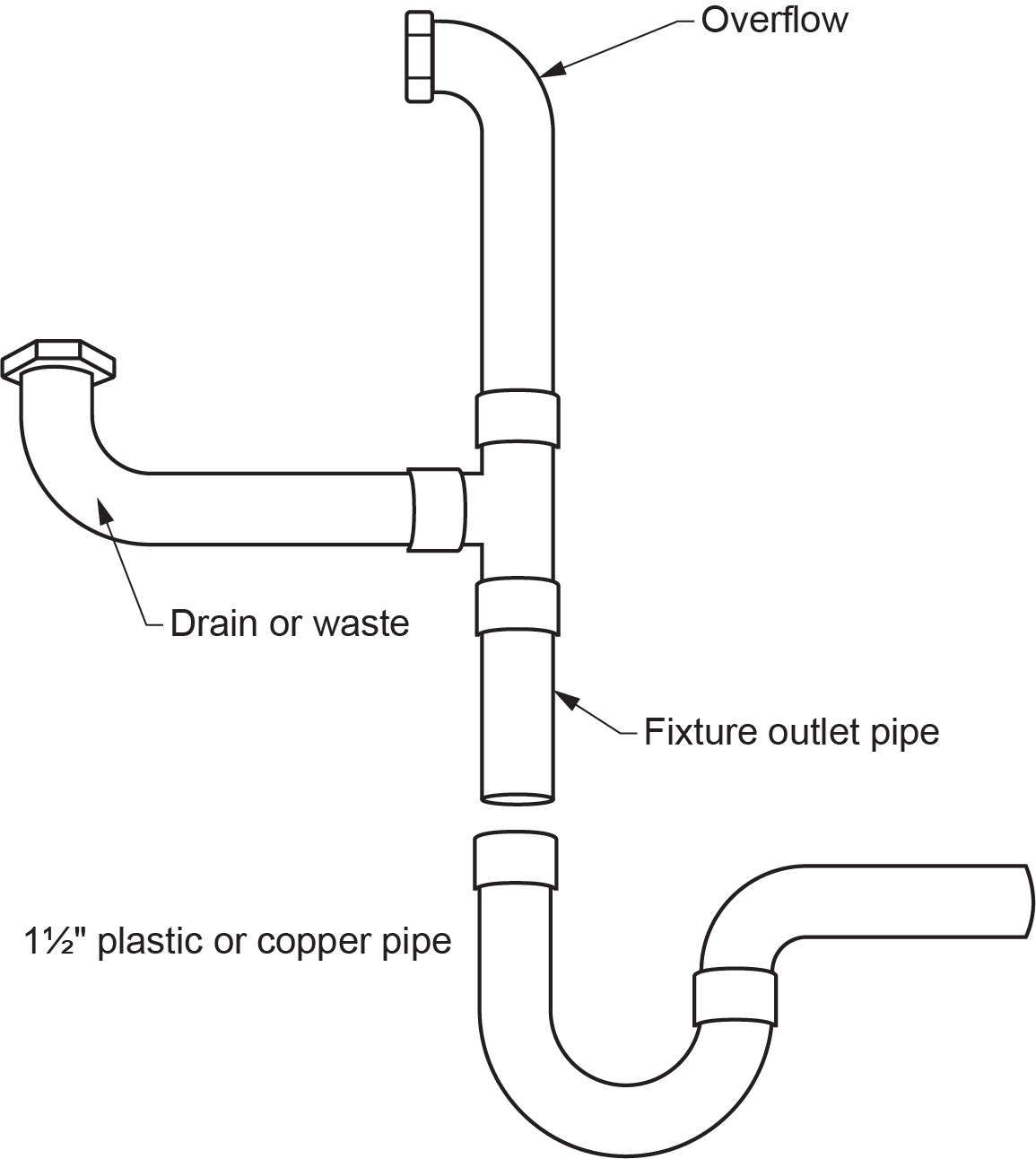
- After the drainage system has been tested, inspected, and approved, connect the bathtub drain. Connect the [latex]1\tfrac{1}{2}[/latex] in. (38 mm) fixture outlet pipe of the waste and overflow fitting to the inlet of the P-trap below the bathtub (Figure 24).

Figure 24 Bathtub connections to the drainage system. (Skilled Trades BC, 2021) Used with permission. - Plug the tub outlet and fill the bathtub with water so that the water level is higher than the overflow. Allow the water to flow out of the overflow.
- Check that there are no leaks in the overflow.
- Drain the tub and check that there are no leaks in the drainage piping.
Installing Water Closets and Urinals
The closet flange is essentially the only support for a floor-mounted water closet (aside from the floor itself ). The measurement to locate a water closet flange should be taken from the rough back wall to the centreline of the final location. Remember to allow for the final thickness of the wall finishing (drywall, plaster or wall tile) when using the dimensions given on rough-in sheets.
Figure 25 shows rough-in information for locating a closet flange and installing a water closet. Notice that the closet flange dimensions and water closet dimensions are shown from the finished wall.
The waste piping should have been roughed in to the point where the floor flange can be installed at the location indicated on the rough-in drawing. The flange is attached to the drain piping and bolted to the floor. Code requirements specify the type of material that the flange and screws are to be made of.
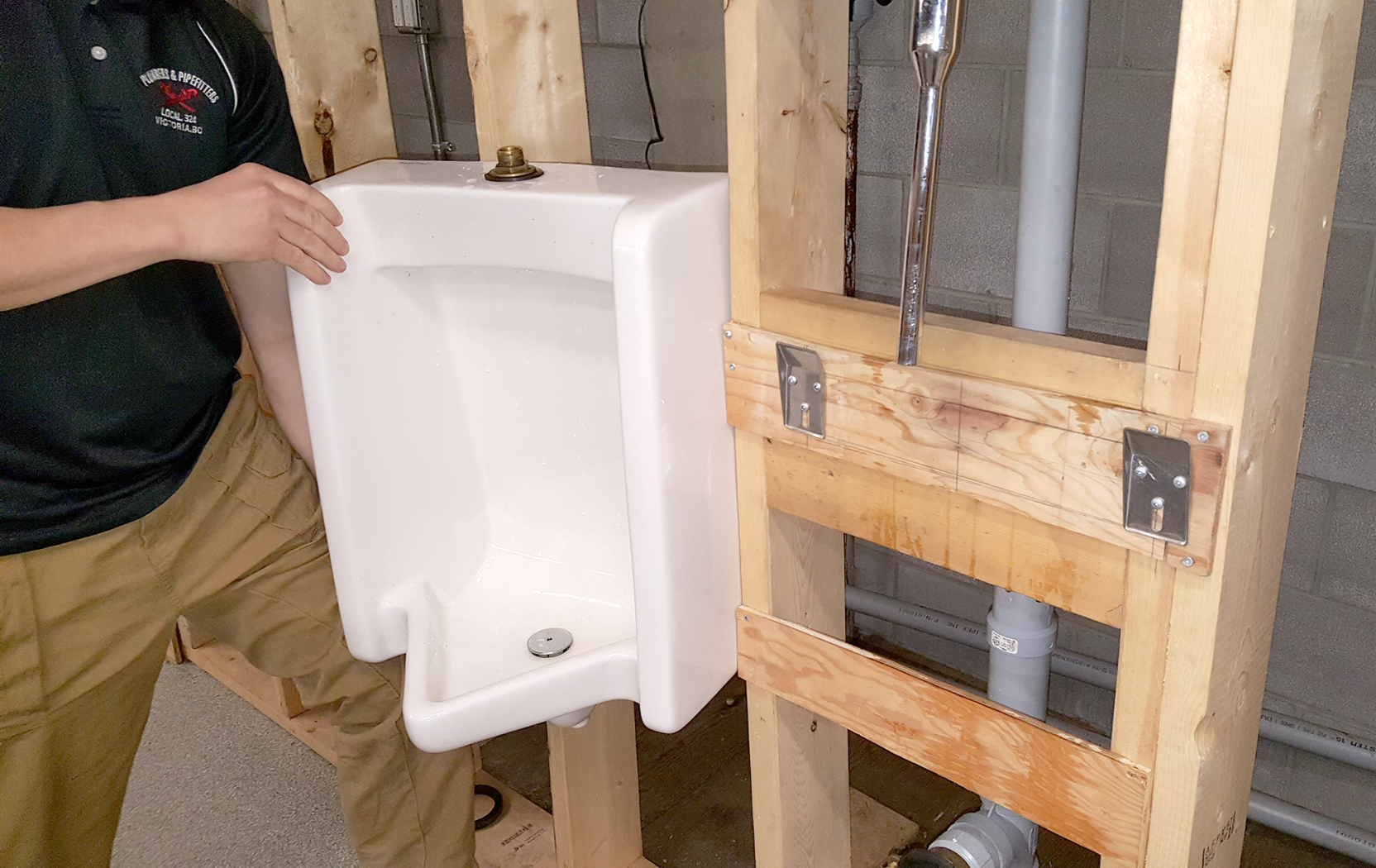
Wall-hung water closets require support from chair carriers (Figure 26) similar in design to the arm carriers used to support some lavatories. Chair carriers provide steady support to the fixture and prevent any weight from resting on drain piping, the wall, or the wall flange. Detailed specifications for installing chair carriers are provided by each manufacturer.

Installing a Floor-Mounted Water Closet
The rough-in work for the water closet should be complete before installation. The closet flange should be secured to the floor and connected to drainage piping. The supply piping should be available at the correct location. In new construction, the finished flooring is always installed before the water closet.
Install a standard supply stop. The cold water supply to the toilet tank is generally connected to a [latex]\tfrac{1}{2}[/latex] in. (13 mm) copper or PEX supply pipe with a [latex]\tfrac{3}{8}[/latex] in. (9.5 mm) flexible tube or hose. The stop is mounted 150 mm (6 in.) to the left of the centreline of the water closet and about 150 mm (6 in.) above the finished floor.
The steps to install a water closet are:
- Slip the heads of the two closet bolts into the slots in the closet flange. Centre them on each side of the flange at equal distances from the rear wall. (This step may have been completed during rough-in.) Closet bolts must be made of brass or plastic.
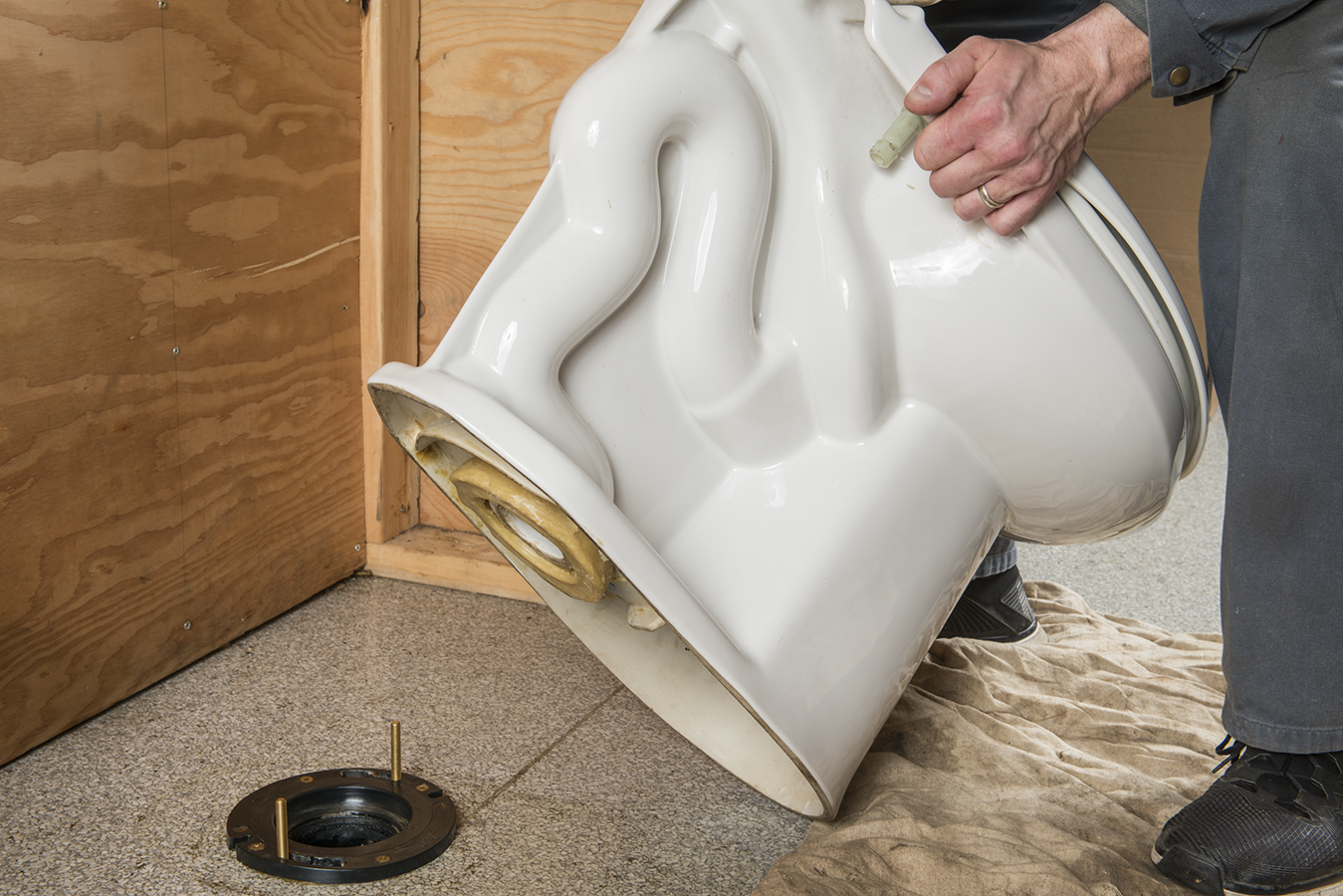
- Place the water closet onto the closet flange, and check that it is level. Gently try to rock the bowl. If it rocks even slightly, shim the fixture until it is stable. A slight wobble can eventually break the seal between a water closet and the closet flange.
- Remove the test plate from the closet flange. Install a wax ring or gasket on the closet flange on the floor or on the horn of the closet. (Some wax seals have a plastic sleeve called a horn that extends from the bottom of the closet outlet into the opening of the closet flange.) The wax ring should stand at least 19 mm ([latex]\tfrac{3}{4}[/latex] in.) higher than the finished floor.
- Lower the fixture onto the closet flange (Figure 28). Rock the bowl gently to squeeze out and distribute the wax.
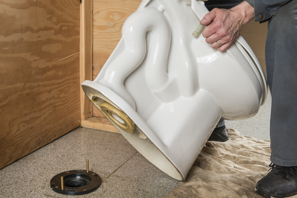
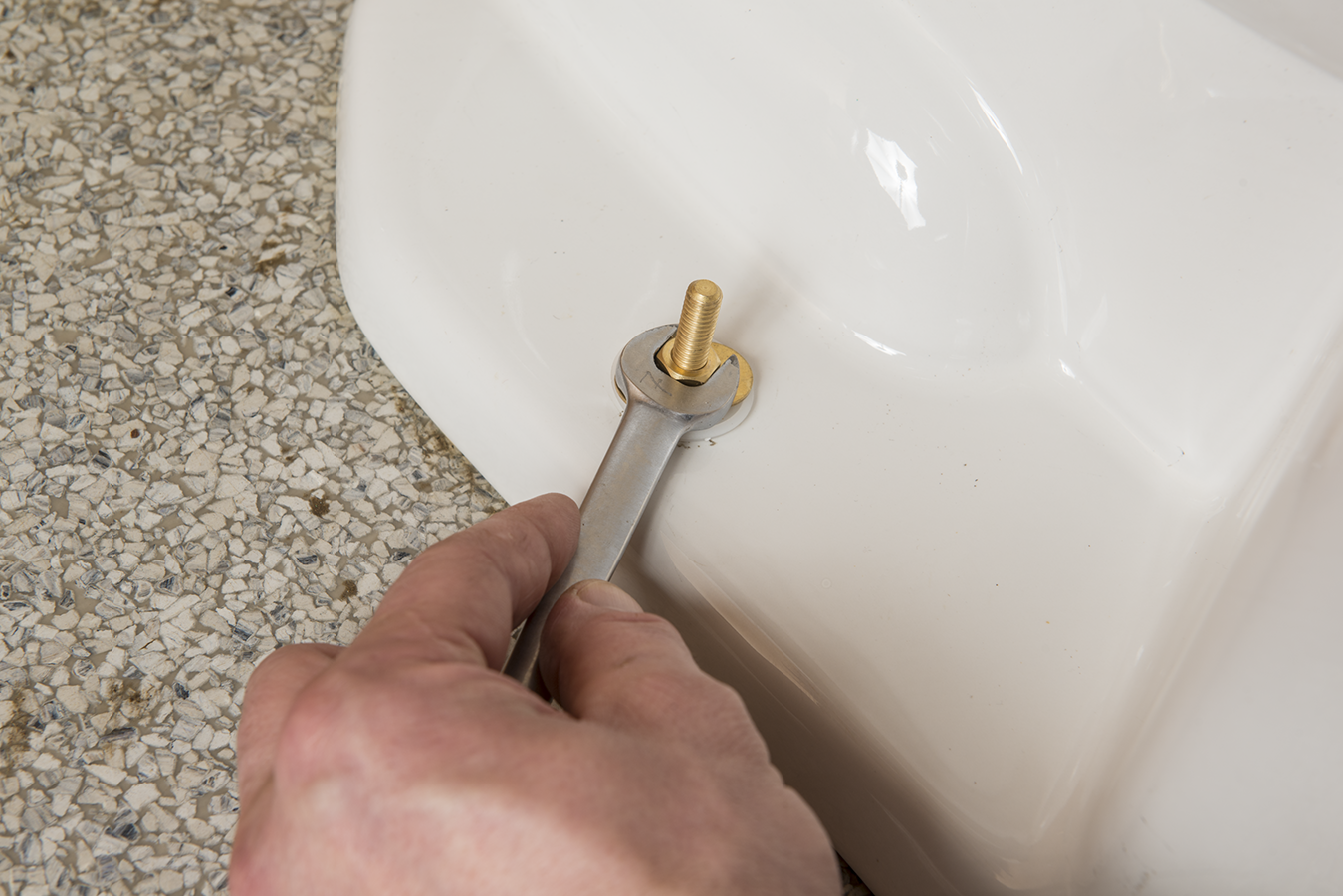
Figure 28 Placing toilet. (Skilled Trades BC, 2021) Used with permission. - Cap the brass closet bolts. Drop metal closet washers over the bolts and tighten nuts to hold them in place (Figure 29). Cut the bolts shorter and place caps over the bolt ends.

Figure 29 Tighten nuts. (Skilled Trades BC, 2021) Used with permission. - If the water closet is a one-piece type with a moulded water tank, simply attach the water supply tubing or hose. For a separate, close-coupled tank, install the large, formed sponge rubber “tank to bowl” gasket over the threaded outlet on the bottom of the tank, and insert the tank mounting bolts complete with sealing washers in through the top of the tank (Figure 30). Lower the tank onto the bowl so that the tapered end of the gasket fits evenly into the bowl water inlet opening, and the tank mounting bolts go through the mounting holes in the bowl. Secure the tank with washers and nuts, ensuring that the tank is parallel to the wall. Tighten the nuts alternately until the tank contacts the front and back of the bowl, making china-to-china contact.
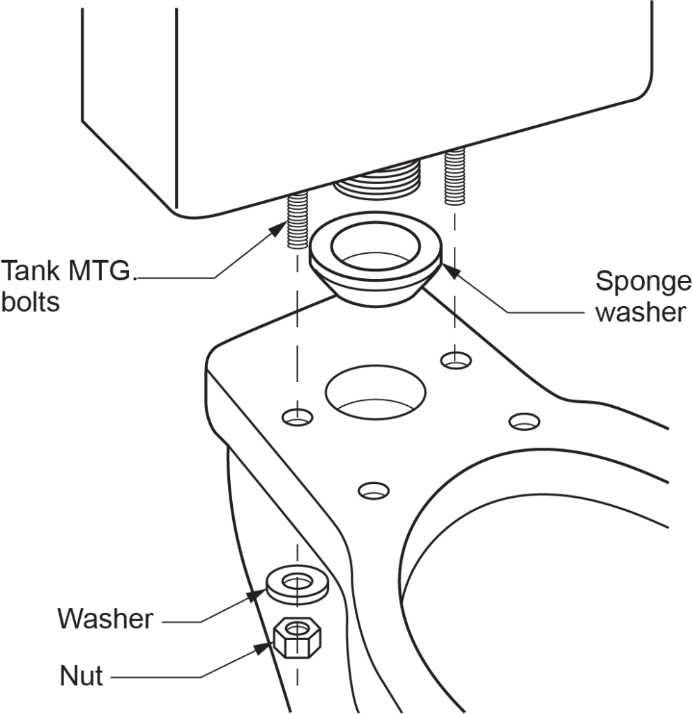
Figure 30 Close coupled tank. (Skilled Trades BC, 2021) Used with permission. - When the water supply is hooked up and the tank is in place, test the water closet for leaks.
- Hold the ball-cock in the closed position and turn the water supply stop so that water is supplied at full force. Check for leaks at the stop and at the connection to the tank. When you are sure the water supply is free of leaks, install the toilet seat.

Backing for Bathroom Accessories
Bathroom accessories may be attached to the finished wall with toggle bolts, or they may require additional backing. Shower curtain rods, toilet paper holders, soap dishes and dispensers, and towel bars will be more secure if attached through the finished wall to backing boards. Grab bars or handrails must be securely bolted to backing that is sufficient to support a person’s weight and any expected pull forces that may be imposed upon them (Figure 31).

Installing Sinks
Sinks may have one or two compartments and use different configurations of faucets and drains. Some sinks are self-rimming and are sealed or clamped directly onto the countertop. Others require a metal frame called a sink rim that is attached to the sink then clamped to the counter. Undermount sinks are very popular, and their installation is a little more complicated, as they require a structure strong enough to support the weight of the sink filled with water. Mounting methods can include epoxied clips, rail systems, brackets, or wood support frame. Faucets may be installed in a back rim or in countertop holes.
Mounting Sink Faucets
Templates or exact dimensions for cutting countertop holes for faucets are usually supplied by the manufacturer. If they are not, follow the tracing procedure described in the previous description of installing lavatories. Due to the many different specialty countertop materials, the cabinet and/or countertop suppliers often prefer to cut the holes and even mount the sink.
If the sink has no ledge and the faucets mount directly into the countertop, install them before mounting the sink in the countertop. Otherwise, perform the following steps after installing the sink.
To install standard kitchen faucets (with no spray attachment), do the following:
- If the faucet body does not have a sealing gasket that rests between the faucet and the deck of the sink, apply plumber’s putty or silicone caulking before inserting the body into the sink holes. This will prevent water from leaking from the sink deck into the cupboard below.
- If you are installing a single-control centre-set faucet design, run a bead of putty under the escutcheon plate and attach it to the sink deck.
- Push the faucets through the ledge. Rock the faucets gently back and forth to compress any putty and seat the faucets.
- If you are installing a single-control faucet, slide the unit and supply tubing through the hole in the escutcheon plate and sink ledge.
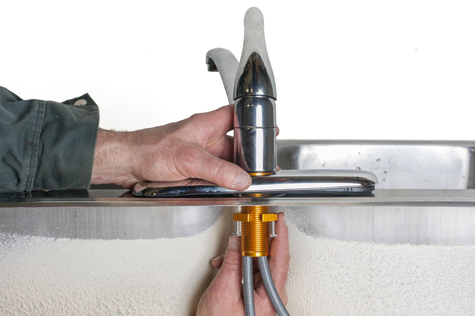
- From under the countertop, place a washer and locknut onto each faucet body and tighten by hand. If you are installing a single-control faucet, tighten a single large washer and locknut onto the underside of the sink deck (Figure 32).
- Tighten each locknut with a basin wrench or adjustable wrench. Apply tension alternately to one and then the other. This will pull the faucets tightly and evenly against the sink edge or countertop. Make sure that faucets stay centred and in line with the sink edge.
- Attach water supply tubing to faucets.
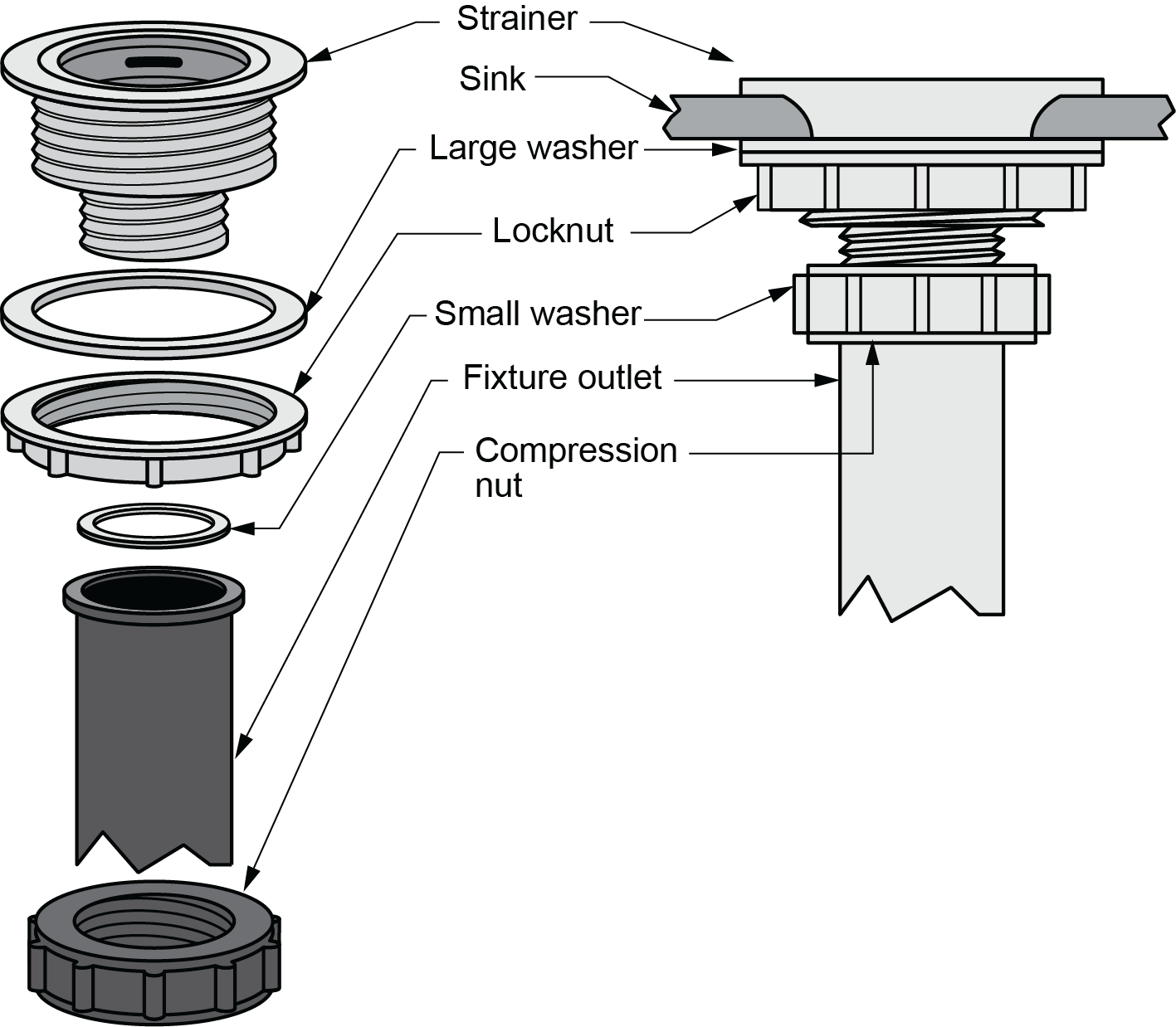
Installing Sink Strainers and Fixture Outlet Pipes
Most kitchen sinks have a centred outlet hole that is about 150 mm (6 in.) in diameter. A metal drain with a [latex]1\tfrac{1}{2}[/latex] in. (38 mm) fixture outlet pipe is seated in the hole and connected to the inlet of a standard [latex]1\tfrac{1}{2}[/latex] in. (38 mm) P-trap. Kitchen sinks also have a basket-type strainer that sits in the metal drain opening to prevent pieces of food from entering and plugging drain piping.
To install a standard basket-strainer drain and fixture outlet pipe:
- Place a bead of plumber’s putty, silicone sealant, or thin rubber gasket around the underside of the strainer flange (Figure 33). Insert the strainer body into the sink outlet opening from above.
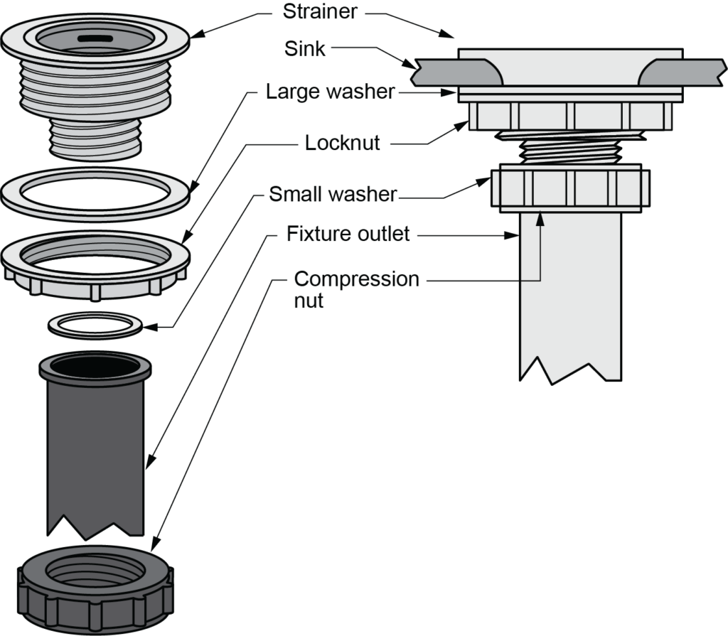
Figure 33 Kitchen sink basket strainer and drain assembly. (Skilled Trades BC, 2021) Used with permission. - Install a large rubber washer from under the sink, sliding it over the portion of the drain that protrudes under the sink. A friction washer is used to hold the washer against the sink and to stop the locknut from binding onto the rubber washer.
- Tighten the locknut on the fixture outlet pipe until the rubber washer (or metal friction washer) is compressed against the sink. This will also pull the flanged lip of the drain against the sink outlet, distributing the putty and sealing the edges. Some plumber’s putty will be visible near the sink outlet.
- Remove any excess putty with a paper towel.
- Place a flared plastic washer into the opening of the flared chromed fixture outlet pipe. Connect the [latex]1\tfrac{1}{2}[/latex] in. (38 mm) fixture outlet pipe to the bottom of the strainer drain. Put a slip nut on the fixture outlet pipe, slide a [latex]1\tfrac{1}{2}[/latex] in. (38 mm) washer on and then tighten the slip nut to connect the tubing ends.
Installing Sinks and Connecting Piping
With the faucets installed and the strainer drain and fixture outlet pipe in place, you can mount the sink in the countertop. All sinks must be sealed so that water cannot seep underneath. As previously mentioned, undermount sinks are often mounted by the countertop supplier.
Some drop-in sinks have sealant applied by the manufacturer. If not, run a bead of silicone sealant under the lip of the sink before it is installed.
To install a drop-in sink:
- Turn the sink upside down and run a bead of sealant along the edge flange of the sink that will rest on the countertop. If you are installing a stainless steel sink, you may prefer to put sealant around the cutout in the countertop and then place the sink on it.
- Centre the sink in the cutout hole and press it down gently onto the countertop. If the sink must be held in place with clamps, gradually tighten the clamps. Apply pressure evenly and be sure not to overtighten. The fixture should be held tightly and evenly on the countertop.
- Use paper towels to remove any excess sealant that has been forced out along the perimeter of the sink. If possible, allow the sealant to set fully before completing your installation. This prevents the sink from shifting.
- Connect the water supply lines to the faucet stops. Hot and cold water supply lines are usually joined by compression fittings.
- Connect the fixture outlet pipe to the P-trap and drain piping. For a two-compartment sink, a continuous waste should be connected to the fixture outlet pipe and the trap with [latex]1\tfrac{1}{2}[/latex] in. (38 mm) slip nuts and bevelled washers.
The procedures for testing the sink for leaks and proper faucet and drain operation are exactly as outlined for testing lavatories.
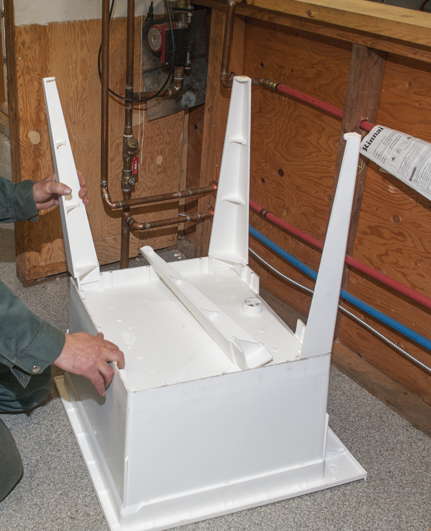
Installing Laundry Trays (Laundry Tubs)
Laundry trays may have one or two compartments. They have support legs and/or may be hung from supports on the wall. Installation usually consists of slipping together component parts (in some models) and attaching the fixture to studs or a wall backing with bolts (Figure 34).
Faucets, drains, and fixture outlet pipes on laundry trays are similar to those for kitchen sinks. Faucets can be deck-mounted on brackets attached to the fixture or anchored to the fixture’s vertical backsplash. Drain fittings and fixture outlet pipes are [latex]1\tfrac{1}{2}[/latex] or 2 in. (38 or 51 mm) in diameter, and outlet drains are installed in the same way as the basket strainer drains found in kitchen sinks. Drains on laundry tubs usually have a cross-piece of metal slightly recessed in the mouth of the drain to prevent large pieces of dirt or debris from entering the drain. A rubber stopper may be used when the trays are to be filled with water. Test the laundry tray the same way you tested lavatories and sinks.
Uncrating and Checking Fixtures
Check the condition of plumbing fixtures as soon as you receive them at the work site. Although care is taken when packaging expensive fixtures, damage may occur during transport. If you find scratches, defects, or breaks, make a note on the packing slip and invoice at the time of delivery. Notify the shipping company or the manufacturer immediately to ensure that replacements arrive quickly.
Fixtures that are not installed immediately should be stored in their packing crates. Manufacturers often mark the position in which the crate should be stored. When you are ready to install the fixture, move the crate to the job site and unpack the fixture.
Although fixtures are strong, they are easily damaged if handled roughly or too frequently. Protect the finish of each fixture during the entire installation. Lay down cardboard or other protective material on the floor. Uncrate the fixture and place it on the protective floor covering. Check it carefully just before installing to ensure that no damage has occurred. Any damage must be reported to a supervisor immediately.
The packing frame for heavier fixtures, such as bathtubs, may be saved to use after installation. Because tubs are installed during the rough stages of construction, they must be protected from damage as building continues. Plumbers often like to re-attach bathtub frames and packaging after the tub is installed to protect the fixture until it will be used by the owner.
Installation Hazards
Take new plumbing fixtures out of packing crates carefully. Crates may be fastened with wire that can injure workers if the tension on the wires is released suddenly. Packing staples are a hazard when fixtures are packed in heavy cardboard boxes. Staples are sharp and long and can cause painful cuts or punctures as well as damage to the fixtures. The tools used to unpack fixtures can also present a hazard if handled incorrectly. Sharp knives or cutters must be handled with care.
Muscle strain is an ever-present hazard when handling heavy fixtures. Lifting incorrectly or lifting too much weight can cause disabling injuries. Most workplaces have information available about back safety and proper lifting procedures. Knowledge of safe methods can prevent most of these injuries. If you cannot find this information at your workplace, contact WorkSafeBC.
When installing fixtures and connecting trim, plumbers are often on their backs or working above their heads. Whenever you have to work below a fixture or piping, there is always a chance that material can fall and cause injuries to your eyes or face. You may be soldering piping or using toxic solvents. If safe procedures are followed and adequate ventilation is provided, the chances of injuries from burns or chemicals will be minimized.
You will often work on scaffolds, ladders, or other platforms. The danger of injury increases when safe working procedures are not followed. All working platforms should be properly positioned and secured.
Tools, such as wrenches and pipe cutters, can also present hazards if used improperly. Unused pipes, fittings, or fixture components left unorganized around a work site can present problems. Proper precautions and safe working habits can prevent many of the common injuries that occur at work.
Customer Relations
Fixtures are expensive and may be easily damaged if handled roughly. Even after installation, fixtures should still be protected. Bathtubs and showers are often installed in the early stages of construction, and there is a greater chance that they will be damaged. Cover fixtures with cardboard, cut from packing cartons.
Before leaving an installation, thoroughly inspect all fixtures and test their operation. Make sure hot and cold water runs freely, supply pressures are adequate, and each fixture drains quickly and completely. Clean the work areas and the fixtures thoroughly to leave a more professional appearance. Have the owner or general contractor inspect the fixtures for damage or flaws.
Damage done after that time is not the responsibility of the plumber. Take the time to explain the operation of any unusual controls to the owner. Discuss proper care and maintenance of fixtures and give the owner any warranty or operating instructions.
 Self-Test C-1.2: Fixture and Trim Installation
Complete Self-Test C-1.2 and check your answers.
If you are using a printed copy, please find Self-Test C-1.2 and Answer Key at the end of this section. If you prefer, you can scan the QR code with your digital device to go directly to the interactive Self-Test.

References
Skilled Trades BC. (2021). Book 2: Install fixtures and appliances, install sanitary and storm drainage systems. Plumber apprenticeship program level 2 book 2 (Harmonized). Crown Publications: King’s Printer for British Columbia.
Trades Training BC. (2021). C-1: Install fixtures and trim. In: Plumber Apprenticeship Program: Level 2. Industry Training Authority, BC.
Media Attributions
All figures are used with permission from Skilled Trades BC (2021) unless otherwise noted.
The minimum space required between fixtures and walls or other structures, as regulated by codes and specifications. (Section C-1.2)
Support materials (e.g., plywood, lumber, metal) installed behind finished walls to secure fixtures like lavatories and shower curtain rods. (Section C-1.2)
Steel frames used to provide additional support for fixtures such as wall-hung water closets, especially for persons with disabilities. (Section C-1.2)
A fitting used to anchor the showerhead securely to the wall, often with a female iron pipe thread (FIP). (Section C-1.2)
A decorative cover or plate used in plumbing to hide gaps or holes around pipes, faucets, or other fixtures. It helps make the area look neat and clean by covering the space where a pipe or fixture meets the wall or surface. Escutcheons are often used in sinks, showers, and toilets to improve the appearance and prevent water from leaking behind the fixture. (Section C-1.1)
A valve used to blend hot and cold water, controlling the flow to a bathtub or shower. (Section C-1.2)
A valve in a combination tub-shower fixture that directs water either to the tub spout or the showerhead. (Section C-1.2)
Plumbing components that connect the bathtub drain to the trap, preventing overflow. (Section C-1.2)
A fitting that connects the water closet to the waste pipe, ensuring a secure connection. (Section C-1.2)
A U-shaped pipe that prevents sewer gases from entering a home by trapping water. (Section C-1.2)
A vertical section of pipe for washing machine drainage, ensuring proper waste disposal. (Section C-1.2)
A recessed box that simplifies connections for washing machine supply lines and drainage. (Section C-1.2)
A network of pipes that remove wastewater and provide ventilation to prevent sewer gases from entering buildings. (Section C-1.2)
In construction, means cutting a small section out of wood or another material to help pieces fit together properly. It is often done to make space for pipes, wires, or to join beams and boards securely. (Section C-1.1)
A classification system indicating how long a barrier (e.g., firewall, floor) can prevent the spread of fire. (Section C-1.2)
Drawings that provide room dimensions, fixture arrangements, and building materials, serving as a primary reference for rough-in work. (Section C-1.2)
Plans that indicate load-bearing elements of a building, ensuring that plumbing modifications do not weaken the structure. (Section C-1.2)
Plans that depict the layout of supply piping, waste and vent lines, and other mechanical systems within a building. (Section C-1.2)
Diagrams showing the layout of electrical lines, outlets, and fixtures to prevent conflicts with plumbing installations. (Section C-1.2)
A detailed plan showing the exact placement of pipes, fittings, and connections needed for plumbing installations. (Section C-1.2)
A three-dimensional technical drawing that illustrates the layout, connections, and travel path of plumbing pipes. (Section C-1.2)
A document that includes technical details about a fixture, including rough-in dimensions and installation requirements. (Section C-1.2)
Manufacturer-provided specifications detailing fixture dimensions, pipe connection points, and installation guidelines. (Section C-1.2)
Reference lines used in plumbing rough-in to accurately position piping and fixture supports. (Section C-1.2)
Metal brackets used to support wall-hung fixtures, ensuring they are securely attached to the wall structure. (Section C-1.2)
A small shutoff valve installed at the water supply stub to control water flow to a fixture. (Section C-1.2)
A plumbing connection method that uses a nut and ferrule to create a watertight seal on supply lines. (Section C-1.2)
A sealing material used to prevent leaks between two surfaces, such as between a faucet and sink. (Section C-1.2)
A drain mechanism with a pivot rod that allows the stopper to be raised or lowered using a lift rod. (Section C-1.2)
A threaded fastener used to secure plumbing fixtures and fittings in place. (Section C-1.2)
A pliable sealing compound used to create watertight seals around drains and fixtures. (Section C-1.2)
A type of sink supported by a freestanding pedestal that conceals plumbing connections. (Section C-1.2)
A flexible sealant used to waterproof joints and seams, especially in synthetic materials where putty may cause staining. (Section C-1.2)
A sink with a built-in lip or rim that rests on the countertop, requiring minimal installation support. (Section C-1.2)
A continuous bed of mortar used to support the bottom of certain types of bathtubs, such as jetted tubs and whirlpools. (Section C-1.2)
A pipe fitting with mounting wings that allows secure attachment to a backing board, commonly used for shower and tub spouts. (Section C-1.2)
A vertical pipe that connects to the shower arm and directs water to the showerhead. (Section C-1.2)
A type of shower arm fitting with mounting ears for secure attachment to wall framing. (Section C-1.2)
A seal placed on the back of the bathtub overflow opening to prevent leaks. (Section C-1.2)
The rear edge of a bathtub that is supported by a horizontal ledge to provide stability and prevent movement. (Section C-1.2)
A raised edge on a bathtub or shower base that sits behind the finished wall to prevent water from seeping behind the unit. (Section C-1.2)
